


12 SUPER-X PRO CX2310
13 Quick Start Guide
(INPUT) (INPUT)
(INPUT)
(CLIP)(CLIP)
(CLIP) (LOW CUT)
(LOW CUT) (LOW CUT)
(LOW/MID)
(LOW/HIGH) (LOW/HIGH)
(LOW OUTPUT)
(HIGH OUTPUT)
(MID/HIGH)
(LOW OUTPUT)
(HIGH OUTPUT)(MID OUTPUT)
(HIGH OUTPUT)(LOW OUTPUT)
(1) (2) (3) (4) (6)(5)(7) (9)(8) (11)(10) (13)(12)
(4)
(9)(8) (7) (1) (2) (3) (5) (6)
(INPUT) (INPUT)
(INPUT)
(CLIP)(CLIP)
(CLIP) (LOW CUT)
(LOW CUT) (LOW CUT)
(LOW/MID)
(LOW/HIGH) (LOW/HIGH)
(LOW OUTPUT)
(HIGH OUTPUT)
(MID/HIGH)
(LOW OUTPUT)
(HIGH OUTPUT)(MID OUTPUT)
(HIGH OUTPUT)(LOW OUTPUT)
(1) (2) (3) (4) (6) (5) (9) (8) (15) (17) (16) (9)(8)
(7) (14) (11)
(10) (13) (12)(7)(7)
(6)
(1) (2) (4)
(3)(7) (8) (5)
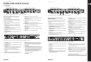
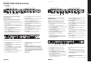
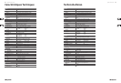
Stereo 2-way operation with separate
subwoofer signal
First, activate the 2-way mode using the MODE switch on the rear panel
(switch depressed). The STEREO LED on the front panel above the LOW CUT
switch in the second channel lights up.
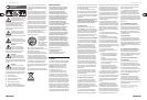
(1) INPUT control. This control adjusts the input gain over the range
from -12 to +12 dB.
(2) LOW CUT switch. This switch activates the 25 Hz high-pass lter.
It has a side gradient of 12 dB/octave and is used to protect your
bass loudspeaker.
(3) LOW/HIGH XOVER FREQ. control. This control governs the crossover
frequency between the low and high bands.
(4) LOW OUTPUT control. Controls the output level of the low band over the
range from -6 to +6 dB.
(5) LOW PHASE INVERT switch. This switch reverses the polarity of the
low output.
(6) LOW MUTE switch. This is used to mute the low band.
(7) HIGH OUTPUT control. This controls the output level of the high band over
the range from -6 to +6 dB.
(8) HIGH PHASE INVERT switch. This switch reverses the polarity of the
high output.
(9) HIGH MUTE switch. This is used to mute the high band.
(10) XOVER FREQ. control. This control governs the crossover frequency between
the low signal and the subwoofer signal (10 to 235 Hz).
(11) GAIN control. This is used to set the subwoofer output volume at the
SUBW. OUT output.
(12) PHASE INVERT switch. This switch reverses the polarity of the subwoofer
output signal.
(13) MUTE switch. This mutes the subwoofer output signal.
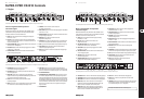
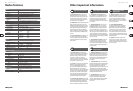
(1) HIGH OUTPUT connectors. These are the balanced XLR connectors for the
high band output signal.
(2) LOW OUTPUT connectors. These are the balanced XLR connectors for the
low band output signal.
(3) XOVER FREQ. switch. These switches are used to switch between the
control ranges on the front panel LOW/HIGH XOVER FREQ. control.
The range is either 44 to 930 Hz or 440 Hz to 9.3 kHz.
(4) INPUT connectors. These are the balanced XLR connectors for the
input signal.
(5) MODE switch. In stereo 2-way operation the switch must be depressed.
Please refer to the text on the rear panel of the equipment.
(6) SUBW. OUT connector. This is the balanced XLR output for the mono
subwoofer signal. This signal is constant in mono and stereo mode and
provides an additional means of providing 2- and 3-way operation.
(7) IEC-RECEPTACLE.
(8) FUSE HOLDER /VOLTAGE SELECTOR. Before connecting the equipment
to the mains supply, please check that the voltage display conforms with
your mains voltage supply. When replacing the fuse, make sure you use
another one of the same type. With many units the fuse holder can be set
in one of two positions, in order to switch between 230 V and 115 V.
Please note: if you wish to operate a unit outside Europe,
then a stronger fuse must be used.
(9) SERIAL NUMBER.
Active control elements on the front panel of the SUPER-X PRO in stereo 2-way operation with separate subwoofer signal
Active control elements and connections on the rear panel of the SUPER-X PRO in stereo 2-way operation with separate subwoofer signal
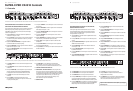
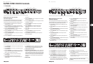
Mono 3-way operation with separate
subwoofer signal
First activate mono 3-way mode using the MODE switch on the rear panel
(switch released). The MONO LED on the front panel above the LOW CUT
switch lights up.
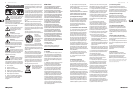
(1) INPUT control. This control adjusts the input gain from -12 to +12 dB.
(2) LOW CUT switch. This switch activates the 25 Hz high pass lter.
(3) LOW/MID XOVER FREQ. control. This control governs the crossover
frequency between the low and middle bands.
(4) LOW OUTPUT control. This controls the output level of the low band over
the range -6 to +6 dB.
(5) LOW PHASE INVERT switch. This switch is used to reverse the polarity
of the low output.
(6) LOW MUTE switch. This is used to mute the low band.
(7) MID/HIGH XOVER FREQ. control. This control governs the crossover
frequency between the mid and high bands.
(8) MID OUTPUT control. This is used to control the output level of the mid band
over the range -6 to +6 dB.
(9) MID PHASE INVERT switch. This reverses the polarity of the mid output.
(10) MID MUTE switch. This is used to mute the mid band.
(11) HIGH OUTPUT control. This controls the output level of the high band over
the range from -6 to +6 dB.
(12) HIGH PHASE INVERT switch. This reverses the polarity of the high output.
(13) HIGH MUTE switch. This is used to mute the high band.
(14) XOVER FREQ. control. This control governs the crossover frequency
between the low signal and the subwoofer signal.
(15) GAIN control. This sets the subwoofer output volume level at the
SUBW.OUT output.
(16) PHASE INVERT switch. This switch is used to reverse the polarity of the
subwoofer output signal.
(17) MUTE switch. This is used to mute the subwoofer output signal.
Active control elements on the front panel of the SUPER-X PRO in mono 3-way operation with separate subwoofer signal
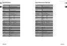
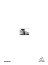
(1) HIGH OUTPUT connector. This is the balanced XLR connector for the high
output signal.
(2) MID OUTPUT connector. This is the balanced XLR connector for the mid
output signal.
(3) LOW OUTPUT connector. This is the balanced XLR connector for the low
output signal.
(4) XOVER FREQ. switch. This is used to switch between the control ranges
of the front panel MID/HIGH XOVER FREQ. control. The range is either
44 to 930 Hz or 440 Hz to 9.3 kHz.
(5) XOVER FREQ. switch. This is used to switch between the control ranges
of the front panel LOW/MID XOVER FREQ. control. The range is either
44 to 930 Hz or 440 Hz to 9.3 kHz.
(6) INPUT connector. This is the balanced XLR connector for the input signal.
(7) MODE switch. This must be de-activated when in mono 3-way operation.
(8) SUBW. OUT connector. This is the output for the mono subwoofer signal.
This signal remains constant in mono and stereo mode and oers an
additional way of providing 2-way and 3-way operation.
Active control elements and connections on the rear panel of the SUPER-X PRO in mono 3-way operation with separate subwoofer signal
(EN) Controls
Check Out behringer.com for Full Manual
SUPER-X PRO CX2310 Controls