


6
SUPER-X PRO CX2310
2. CONTROL ELEMENTS
+ If the unit is damaged, please do not return it to us, but notify your dealer and the shipping
company immediately, otherwise claims for damage or replacement may not be granted.
Shipping claims must be made by the consignee.
Be sure that there is enough space around the unit for cooling and please do not place the SUPER-X PRO on
high-temperature devices such as power amplifiers, etc. to avoid overheating.
+ Before connecting the SUPER-X PRO to the mains, please carefully check that your equipment
is set to the correct supply voltage!
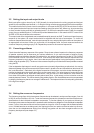
The fuse holder on the female mains connector has 3 triangular markings. Two of these triangles are opposite
each other. The CX2310 is set to the operating voltage shown next to these markings. It can be set to another
voltage by turning the fuse holder through 180°. CAUTION: this does not apply to export models, which
were designed e.g. only for a mains voltage of 115 V!
Connection to the mains is made by means of a mains cable with an IEC receptacle which complies with the
appropriate safety regulations.
+ Please note that all units must be grounded properly. For your own safety, you should never
remove any ground connectors from electrical devices or power cords or render them
inoperative.
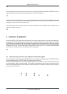
2. CONTROL ELEMENTS
Since the SUPER-X PRO offers a variety of features, we have provided the active controls with suitable light-
emitting diodes. These displays help you to keep track of what is happening even in dark stage environments.
Additionally, all the switches on the front panel are illuminated and can thus show which functions are presently
active. There are two labels in the form of strips, located above the controls. The text of the upper label
indicates mono 3-way, and the lower label indicates stereo 2-way mode. The LEDs set below these labels
show which controls are active in the respective mode of operation.
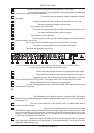
+ On the rear panel, labels above/below the connectors refer to the various crossover modes
available. Please make sure that the MODE switch and corresponding connectors are
configured properly; otherwise, you could damage your speakers.
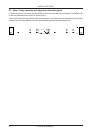
2.1 Stereo 2-way operation with separate subwoofer signal
First, activate the 2-way mode using the MODE switch on the rear panel (switch depressed). The STEREO LED on
the front panel above the LOW CUT switch in the second channel lights up.
The LEDs above the active control on the front panel then light up. They show you which controls are active for the
mode of operation, which you have selected. The functions of these controls can be seen from the second strip
label. In stereo operation the functions of both channels are identical, so that the numbers on the overview are
shown for only one channel.