


8
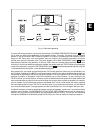
1.3 Control elements
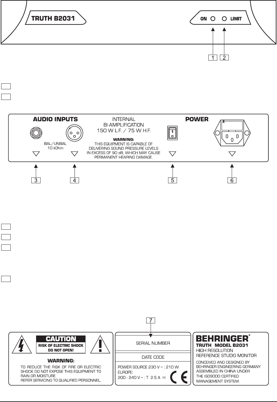
The control elements described in the following are the same on both speakers.
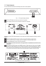
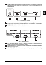
Fig. 1.1: Front panel display elements
1
ON
. This LED lights up as soon as you switch on the speaker.
2
LIMIT
. Lights up as soon as one of the built-in protections is activated.
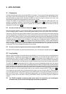
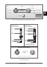
Fig. 1.2: Rear panel input connectors
All connectors of the TRUTH face downwards, so as to allow you to place the speaker as closely to a wall as
possible.
3
INPUT
. This balanced TRS connector is used to connect the speaker to a signal source.
4
INPUT
. This XLR connector is used to connect the speaker to a balanced signal source.
5
Use the
POWER
switch to put the TRUTH into operation.
+ The TRUTH should be the last device in the signal chain to be switched on and the first to be
switched off.
6
FUSE
holder
/VOLTAGE
selector and
MAINS
connector. Please make sure that your local voltage
matches the voltage indicated on the unit, before you attempt to connect and operate the TRUTH.
Blown fuses may only be replaced by fuses of the same type and rating. Use the enclosed power cord
to connect the unit to the mains. Please note the instructions given in chapter 3 “INSTALLATION”.
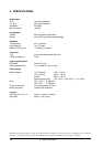
Fig. 1.3: The serial number of your TRUTH
1. INTRODUCTION