


Page 2 of 2 75.5116.03 EN 20080505
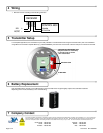
4 Wiring
7 Company Contact
6 Battery Replacement
If the transmitter fails to operate, or the indicator light on the transmitter does not glow brightly, replace the transmitter’s batteries.
Depending on the model, the battery is one of the following:
1. Wire the receiver according to the following schematic:
RECEIVER
RED
BLACK
GREEN
WHITE
CONTROL BOX
ACTIVATION
COMMON
+
24V
AC/DC
-
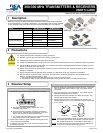
5 Transmitter Setup
For Pushplate applications, the transmitter may be neatly installed in most electrical boxes using the enclosed Velcro pads. For installations
using BEA’s line of Plastic Pushplate Boxes (e.g. 10BOX45RNDSM), use the holes on the inside of the box and pins to hold the circuit board.
Do not leave problems unresolved. If a satisfactory solution cannot be achieved after troubleshooting a problem, please call BEA, Inc. If you must wait for the
following workday to call BEA., leave the door inoperable until satisfactory repairs can be made. Never sacrice the safe operation of the automatic door or
gate for an incomplete solution. The following numbers can be called 24 hours a day, 7 days a week. For more information, visit www.beasensors.com.
US and Canada:
Canada:
Northeast:
1-866-249-7937
1-866-836-1863
1-866-836-1863
Southeast:
Midwest:
West:
1-800-407-4545
1-888-308-8843
1-888-419-2564
TRANSMITTER MOUNTING PINS
(Adjust location for transmitter)
or use Velcro tab to secure
-‘mini’ transmitters
9V BATTERY
BATTERY CLIP