


5
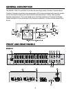
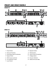
FRONT AND REAR PANEL CONTROLS
1. Power Switch
This switch is pressed to turn power ON, pressing the switch again turns the power off.
Always turn on your equalizer BEFORE your power amplifiers are turned on, and always turn
off equalizer AFTER your power amplifiers have been turned off.
2. Filter Level Controls
Each of these sliders control the output level of each of the 31 (or 15) bandpass filters.
Center detent position is grounded for guaranteed flat response.
3. Filter Range Switch & Indicators
The gain range of the filter sliders is switchable (as a group) from +/-6dB to +/-12dB for
maximum boost/cut capability. When this switch is in the "OUT MOST" position, at 6dB, the
green LED will illuminate. When it is in the "IN MOST" position, at 12dB, the yellow LED will
illuminate.
4. Bypass Switch
When it is the "IN MOST" position, equalizer is bypassed. Its associated LED indicates status.
(See 8. Bypass indicator)
5. HPF Frequency Control (EQA 231 and EQA131)
To cut down unwanted signal, this control determines the roll-off frequency of the High-Pass
Filter. The roll-off frequency can be adjusted from 10Hz to 250Hz by turning this knob.
Because of its high roll-off slope, the HPF can be efficiently used to cut down the "HUM"
from preceding instruments, or to prevent low-frequency resonance.
6. LPF Frequency Control (EQA 231 and EQA131)
To cut down unwanted signal this control determines the roll-off frequency of the Low-pass
filter. The roll-off frequency can be adjusted from 3KHz to 40KHz by turning the knob.
Because of its high roll-off slope, this LPF can be efficiently used to cut down the high-
frequency noise from preceding instruments, or especially used to roll-off high-frequency
sound to obtain a more natural sound in acoustic situations.
7. Level Control
This controls the level of the incoming signal. Turn this control down if the PEAK LED
illuminates steadily. Unity gain can be set by turning this knob its center detent position.
8. Bypass Indicator
When the green LED is illuminated this indicates that the unit or channel is in the bypass
mode. Signal is routed directly from the input to the output without passing through any circuit
(often referred to as "hard-wire bypass").