


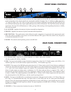
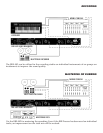
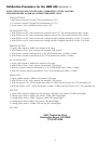
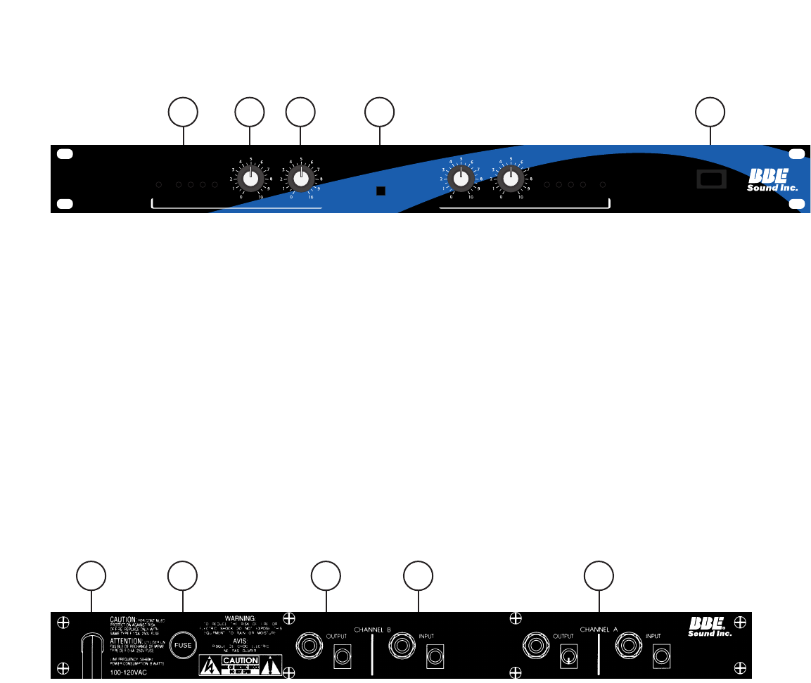
1. LED DISPLAY: The LED display is used to indicate the output signal level of the BBE 482. Each number on the front
panel corresponds to the output signal level, measured in decibels. Example: The “0” indicates a 0dBu signal level,
“-6” refers to -6dBu, and so on. Once an input signal level has been established, increasing the BBE PROCESS and
LO CONTOUR will increase the output signal and cause more LEDs to illuminate. The Clip LED monitors the input
signal level. The Clip LED will illuminate at +15dBu, giving a 3dBu warning of the impending distortion at +18dBu,
the actual clip point.
2. LO CONTOUR: Regulates the amount of phase corrected bass frequencies.
3. PROCESS: Regulates the amount of phase corrected treble frequencies.
4. BBE FUNCTION: This push button switch allows for quick comparison of processed with unprocessed sound.
When the switch is pushed in, the process is on and the indicator LED is green. When the switch is out, the process
is off and the indicator LED is red.
5. POWER: This switch controls primary power to the BBE 482.
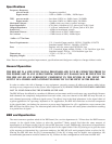
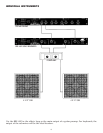
REAR PANEL CONNECTIONS
1. AC POWER CORD: Plugs into AC power receptacle. U.S. Model, 100-120Vac, 50/60Hz.
All other models,220~240Vac, 50/60Hz.
2. FUSE: Turn cap on fuse holder counter-clockwise to remove fuse. (Note: For U.S. Model, replace with 250Vac, 1/2A
Fastblow type fuse. For all other models, replace with 250Vac, .125A Fastblow type fuse.)
3. OUTPUT: The output of the BBE 482 can be taken from the 1/4” Phone Jack or the RCA Jack. Both are unbalanced
and are the same point electronically. This allows both outputs to be used simultaneously, eliminating the need for
a “Y” cord in the event multiple outputs are required. The recommended single load impedance is at least 10k
Ohms. If both outputs are being used, a minimum of a 22k Ohm load per device is required. (The “load” is
determined by the input impedance of the next subsequent component in the signal chain.) The maximum output
is rated at +18dBu. The output impedance of the BBE 482 is 1 k ohms. NOTE: Actual output level will vary due to
the selected position of the BBE Process, and the actual input signal level.
4. INPUT: The input of the BBE 482 is an unbalanced connection. Although is can be either a 1/4” Phone Plug or an
RCA Plug, it is recommended that only one input source is used. Both jacks are the same point electronically,
however, due to the input/output impedance characteristics of most audio devices, a loss of signal may occur and/or
damage to a component if both inputs are utilized. The input impedance of th BBE 482 is 47k Ohms. The maximum
signal level is +18dBu.
5. CHANNEL A: These connections function the same as CHANNEL B.
3
FRONT PANEL CONTROLS
1
1
2
2
3
3
4
4 5
5
CHANNEL A
-
20
-
12
-
6 0 CLIP
-
20
-
12
-
60CLIP
®
FUNCTION
POWER
ON OFF
▼
▼
IN
OUT
BBE PROCESS
SONIC MAXIMIZER
482
CHANNEL B
LO CONTOUR
PROCESS
LO CONTOUR
PROCESS
CALIFORNIA USA
MODEL 482
US PATENT
NO 4,482,866
AND OTHERS