


3
necessary for 2-channel audio, split the signal
into low bass and higher frequencies and feed
the latter back out to the satellite speakers. Left
and right channel inputs may be combined into
a single mono low bass feed to the subwoofer
drive unit if required.
The subwoofer will input and output line-level
signals via the RCA Phono sockets located on
the back panel.
Use the following table to select the correct
wiring method for your installation:
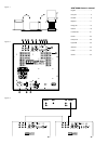
Application: Home Theatre
The subwoofer may be used with any decoder
that has a line-level subwoofer output (normally
from an RCA Phono socket). Most decoders with
integral power amplifiers still output the
subwoofer or Low-Frequency Effects (LFE) signal
at line level.
• Decoder with one or more subwoofers –
fig. 3
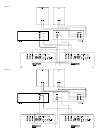
Application: 2-channel audio
Separate pre- & power amplifiers:
a One or more subwoofers with output
combined into a single mono signal – fig. 4
b Two subwoofers with separate left and right
signal – fig. 5
The ASW™2500 is not suitable for use with 2-
channel integrated pre/power amplifiers, unless
they feature a line level output from the pre-
amplifier.
Using more than one subwoofer
Using more than one unit in a single installation
can improve performance in the following ways:
• Maintain stereo separation to the lowest
frequencies.
• Cope with larger listening rooms.
• Enable greater maximum sound output –
often useful for effectively reproducing
special effects in Home Theatre applications.
• Smooth out the effects of low-frequency room
resonances.
If you are using two subwoofers for 2-channel
audio, separation is improved if each channel
has its own subwoofer, providing each one is
placed close to the relevant satellite speaker.
Only use the mono connection of figure 4 if you
cannot place each subwoofer close to its satellite
speaker.
Double-check the connections
ENSURE THAT THE VOLTAGE INDICATED ON
THE AMPLIFIER PANEL MATCHES THAT OF THE
POWER SUPPLY.
Before auditioning the sound quality of your new
installation and fine-tuning it, double-check the
connections. All too often, users complain that
they cannot get a decent sound however they set
the controls, only to discover something has been
wrongly connected. Make sure that:
• The phasing is correct – there should be no
positive to negative connections to the
satellite speakers. If something is out of
phase you may get a fuzzy sound with an
imprecise and floating image, a lack of bass
or a combination of the two.
• There are no left to right mix-ups – this can
result, for example, in the orchestra being the
wrong way round or, more disastrously,
sounds on your Home Theatre going in the
opposite direction to the action on the
screen.
Switching on and off
We recommend that you switch the subwoofer
on before any power amplifiers receiving signals
from the subwoofer. Similarly, when switching
off, switch the subwoofer off last.
The on/auto/standby switch (9) at the top right
of the amplifier panel does not isolate the
amplifier completely from the power supply. It
maintains a low-power input to an auxiliary
sensing circuit. The 230V version of the amplifier
has an additional switch (13) that completely
isolates the power supply. To isolate other
versions, either switch off at the wall outlet or
disconnect the power cord from the amplifier.
We recommend you isolate the subwoofer from
the power supply if it is to be out of use for
extended periods of time.
The switch (9) operates as follows:
On:
With the switch in this position, the amplifier
remains permanently on, and the light glows
green.
Auto:
On first switching the subwoofer to Auto, the
amplifier becomes fully active and the light (10)
above the on/auto/standby switch glows green.
After a period of about 5 minutes without an
input signal, the amplifier automatically reverts to
standby mode, and the light glows red. When
an input signal is detected, the amplifier
automatically becomes fully active and the light
glows green.
Standby:
In this position, the amplifier is in permanent
standby, and the light glows red.
Setting the controls
There are 5 controls to consider:
• The VOLUME control (4)
• The LOW-PASS FREQUENCY control (5)
• The PHASE switch (6)
• The LOW-PASS FILTER switch (7)
• The EQ (equalisation) switch (8)
The optimum settings depend on the other
equipment used with the subwoofer. If using
more than one subwoofer, ensure the controls on
each one are set the same.
Use with home theatre decoders
The ASW™2500 is not a THX
®
licensed
component, but may be used with a THX
®
controller if desired.
• Set the decoder VOLUME control to the half
way (12 o’clock) position.
• The setting of the LOW-PASS FREQUENCY
control is irrelevant.
• Set the PHASE switch initially to 0˚.
• Set the LOW-PASS FILTER switch to OUT.
• Set the EQ switch initially to position A.
See also the section “Fine tuning”.
If you have a THX
®
controller, ensure that the
subwoofer function is enabled. When so
configured it incorporates all the filtering and
level setting required for the subwoofer in all
modes. For level calibration, the internal test
noise and channel level controls in the THX
®
controller should be used. In all cases the levels
should be set to obtain 75dB SPL (C-weighted)
at the listening position from the controller’s
internal noise test signal.
With other decoders, configure the front and
surround speakers to “large” or “small” as
appropriate before setting the levels. Use the
internal noise test signal and volume controls of
the decoder to set the levels of all the speakers.
Only change the VOLUME control on the
subwoofer if there is not enough range in the
decoder to achieve the correct levels.
Inexpensive sound level meters are readily
available from electronics stores and should be
used to calibrate the levels. Refer to your
decoder manual for further details on how to set
the levels.
Use for 2-channel audio
• Set the VOLUME control initially to the half
way (12 o’clock) position.
• Set the LOW-PASS FREQUENCY initially to
80Hz.
• Set the LOW-PASS FILTER switch to IN.
• Set the EQ switch initially to position B.
• Set the PHASE switch initially to 0˚.
See also the section “Fine tuning”.
Fine-tuning
There are two settings of the EQ switch. Position
A is optimised to allow the subwoofer to provide
the highest listening levels, while position B gives
greater bass extension coupled with a tighter
sound.
2-channel audio
The optimum settings of the PHASE switch and
the LOW-PASS FREQUENCY control are inter-
related and also dependent on the low-frequency
cut-off characteristic of the satellite speakers and