


THE BEAUTY OF POWER
B-52 US Series Professional Power Amplifiers - Instruction Manual
US SERIES AMPLIFIERS
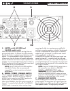
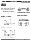
binding posts offer a variety of connection options.
Use speaker wires with stripped ends (do not strip
themmorethan½”or12.5mm),usingtheholeson
thebottomofthebindingposts.Ensurethatnopartof
thespeakerwireisexposedwhenconnectedtothe
bindingposts.Alternatively,youcanalsousespeaker
cablesterminatedwithstandardbananaplugs.Make
sure that no part of speaker wire or banana plugs are
exposedwhenconnectedtothebindingposts.
NOTE: US-Series amplifiers configured for use
inEuropeareprovidedwithpermanentplastic
inserts which prevent using banana plugs for
speaker connection. This is a safety measure
requiredbyEuropeansafetylaws.
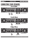
NOTE:IntheBRIDGEDmode,theloudspeaker
must be connected using the two red binding
posts.Thepositive(+)wirefromtheloudspeaker
must be connected to the Channel 1 red post,
and negative (-) wire from the loudspeaker must
be connected to the Channel 2 red post, as
indicated on the rear panel just below the
binding posts.
WARNING:NEVERCONNECTspeakerswith
an impedance lower than the rated minimum
impedance of the amplifier. The lowest
impedanceinSTEREOandPARALLELmodesis
2Ohmsforeachchannel.Thelowestimpedance
inBRIDGEDmodeis4Ohms.NEVER
CONNECT2Ohmsratedloudspeaker(s)or
a combination of speakers to the amplifier in the
BRIDGEDmode.
NOTE:RefertotheCONNECTIONSsection
later in this manual for speaker wire connection
diagrams.
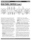
8. SPEAKON™ OUTPUT CONNECTORS
Use these speaker outputs to connect cables fitted with
Speakon™cableconnectors.US-Seriesampliers
have two connectors, one for each channel, to con-
nectSpeakon™ttedcables.The1-pinisconnected
totheground.The1+pinisconnectedtotheoutput
of each channel, which is an industry standard.
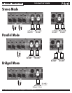
You can connect both channel 1 and channel
2 loudspeakers to the Channel 1 output connector.
To do this a quad speaker cable must be used. The
Channel 1 speaker should be connected to pins
1-/1+andtheChannel2loudspeakerisconnectedto
pins2-/2+.
You can use the Channel 1 output connector for
BRIDGEconnectionofyourloudspeakers(whenthe
amplierisinBRIDGEmode).Inthiscongurationthe
loudspeakersconnectedmustusethe2+pinofthe
connector for the loudspeaker’s ground connection
(NOTCONNECTEDTOTHEGROUNDOFAMPLI-
FIER)andpin1+forthespeaker’sHOTconnection.
REAR PANEL CONTROLS (cont.)
12
1
1
2
2
3
3
4
45 5
6
7
8
9
10