


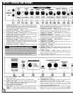
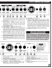

1. LOW/HIGH INPUTS: Plug your guitar in here. Use the input that
best suits your playing style. Most players use the High input for
maximum gain. For a cleaner sound, use the Low input. Always
use a high quality, shielded instrument cable.
2. OVERDRIVE CHANNEL – GAIN 1: Adjusts the amount of
distortion in Gain 1. (Activated LED indicates in use).
3. OVERDRIVE CHANNEL – GAIN SWITCH: Push switch Selects
between Gain 1 and Gain 2 controls. Activated LED lights
indicate which channel is currently use.
4. OVERDRIVE CHANNEL – GAIN 2: Adjusts the amount of
distortion in Gain 1. (Activated LED indicates in use).
5. OVERDRIVE CHANNEL – BASS: Adjusts the amount of low
frequency boost or cut as desired in the overdrive channel. Bass
is B-52’s signature. Turning this control clockwise increases
depth and low-end punch to your music.
6. OVERDRIVE CHANNEL – MIDDLE: Adjusts the amount of
mid-range frequencies as desired in the overdrive channel.
Similar to the Clean Channel function, the O.D. Channel Middle
control adds body and punch to your sound.
7. OVERDRIVE CHANNEL – TREBLE:Adjusts the amount of high
frequency boost or cut as desired in the overdrive channel.
Turning this control clockwise adds clarity to your sound.
8. OVERDRIVE CHANNEL – GAIN SWITCH 1: Activates the
CONTOUR control for Gain 1.
9. OVERDRIVE CHANNEL – CONTOUR: Varies the critical
midrange tone in the overdrive channels. Adjusts from “classic”
midrange punch to “scooped metal” madness.
10. OVERDRIVE CHANNEL – GAIN SWITCH 2: Activates the
CONTOUR control for Gain 2.
11. OVERDRIVE – VOLUME 1: Controls the overall volume of the
medium gain overdrive channel.
12. OVERDRIVE – VOLUME 2: Controls the overall volume of the
high gain overdrive channel.
13. CHANNEL SELECT: Push switch selects between the clean
and overdrive channels. Activated LED lights indicate which
channel is in use.
14. CLEAN CHANNEL - BASS: Adjusts the amount of low
frequency boost or cut as desired. Adding bass will increase the
depth and fullness of your sound.
15. CLEAN CHANNEL - MIDDLE: Adjusts the amount of mid-range
26. AC INLET & PRIMARY FUSE: Connects AC powercord and
houses primary fuse.
Always use correct value as indicated on amp panel chart.
27. POWER TUBE FUSE: This fuse protects the AT-212 against
circuit damage caused by a power tube failure. Only replace
with a 1 AMP Fast Blo (never Slo Blo) fuse.
28. 3-SETTING RECTIFIER SWITCH:
SOLID-STATE – Gives tightest low-end definition and fastest attack.
TUBE AB1 – Punchy, warm and tighter definition than Tube A.
TUBE A – “Vintage” attack and feel. Warmest sounding setting.
29. GROUND / LIFT SWITCH: Removes ground from the circuit
to eliminate 60-cycle hum.
30. LOUDSPEAKER OUTPUTS: Connects the AT-212 to the
speaker cabinets such as the AT-412A or AT-412B.
NOTE: Always be sure the speakers are plugged in before attempting to
operate the amplifier. Always use a high quality, heavy duty, unshielded
speaker cable. Severe damage can occur from failing to connect the speakers
and properly setting the impedance selector switch.
31.
IMPEDANCE SELECTOR SWITCH: Allows the AT-212 to safely
operate into any 4 ohm, 8 ohm or 16 ohm cabinets(s). NOTE:
Always set the switch to match the impedance of your cabinet(s).
To reduce the risk of fire or electrical shock, do not expose this unit to rain
or moisture. Do not operate your AT-212 near a pool or other standing
water. Make sure all blades on the polarized power plug are fully inserted
into the power source. Ensure the powercord is not stretched, pinched or
otherwise abused. Ensure the power cord is routed to avoid foot traffic.
Your AT-212 amplifier should be cleaned only with a dry cloth.
WARNING: SHOCK HAZARD!
4
AT-212 - CONTROLS AND FEATURES