


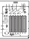

ACT-18X SUBWOOFER FEATURES AND USAGE
1) LEVEL CONTROL: Sets the volume of the subwoofer without influencing the volume of the satellites the satellites, or the full range outputs on the panel mounted XLR connectors.
2) PHASE SWITCH: Allows the user to reverse the direction of excursion at low frequencies. This is to help in getting the subwoofer to move in proper “PHASE” with the satellites, so that the sound in the
cr
ossover region from the satellite and subwoofer add instead of subtract.
3) POWER INDICATOR: The AC Mains Power rocker switch located on the lower left hand side of the amplifier turns on the AC mains power to the amp. A failure to light the Red rocker switch indicates
lack of power and/or a blown AC mains fuse.
4) PROTECTION: This Red LED turns on when there is a fault condition in the system causing circuitry to engage in order to protect the amplifier and prevent it from damaging itself and/or the attached
speaker(s). The most common cause of this is running the amplifier at or near its maximum output level for a very long time. This WILL CAUSE overheating. If protection is engaged because of overheat-
ing, the best course of action is to turn down the level control on the amplifier for long enough (10-15 minutes) to allow the fan to cool it off. After this time if the amp still does not go out of its protect
mode (indicated by the red LED going dim) turn it off for 10 seconds and then turn it on again. If it still does not operate, contact your authorized service provider or B-52.
5) RIGHT & LEFT INPUTS: These XLR connectors accept a balanced input signal cable. The wiring conforms to the Audio Engineering Society standard where Pin 2 is (+) or hot; Pin 3 is (-) or cold; and
Pin 1 is the Shield or ground. The low frequencies are summed because our hearing does not detect direction for very low frequencies, those in the range of the subwoofer. There is therefore, no loss of
stereo image in using a single speaker to reproduce the bass from both channels.
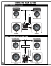
6) RIGHT & LEFT FULL-RANGE OUTPUTS: These connectors are shorted to the INPUTS allowing daisy chaining of the input sig-
nal. Therefore you do not need to y-cable out of your mixer or audio device to get an additional full range signal(s) to another active
system nearby your ACT subwoofer. Use this connector to “daisy chain” multiple systems together.
(See diagram on page 7 for details)
7) RIGHT & LEFT HIGH-PASS OUTPUTS: Sends the high frequency portion (above 120hz) of the full range signal to power ampli-
fication for the full range or mid-high frequency satellite speakers. This signal is the complement of the music signal sent to the sub-
woofer. In other words, it is what is left of the music after the bass has been removed. It is that part of the music which the subwoofer
does NOT reproduce. It should be sent to your active satellite speakers INSTEAD of the full range signal. When the very lowest bass
frequencies are removed from the satellites, this will increase your dynamic range, (let you play it louder) lower your distortion, and
improve the sound of the system relative to what you would hear with the full range signal sent to your high frequency satellites. (See
diagram on page 6 for details)
8) EXTERNAL SPEAKER ON/OFF SWITCH: When using the powered ACT-18X without a second passive subwoofer (the ACT-18XS),
this switch should be in the off position. IF IT IS NOT, THAT WILL REDUCE THE AVAILABLE POWER TO THE SINGLE ACT-18X SUBWOOFER.
When an external, non-powered subwoofer (ACT-18XS) is connected to the ACT-18A, turn this switch on. Do not use this switch unless
the volume control is all the way down (fully counter-clockwise).
9) EXTERNAL SPEAKER OUTPUT: This 4-pin Speakon-style connector is for connecting an ACT-18XS passive subwoofer to the ACT-
18X amplifier
. Either pins 1+ and 2+ can be used as the positive connection. Either pins 1- or 2- can be used as the Negative
Connection. Only connect an ACT-18XS in parallel to the ACT-18X subwoofer!! Use of any sub other than an ACT-18XS will void the war-
ranty and may cause your amplifier to shutdown or fail. When adding subwoofers it is impor
tant that they have the same r
esponse
(magnitude and phase) or one will likely subtract its output from the other (instead of adding) at some point within the range of both.
10) ON/OFF SWITCH: T
ur
ns on the AC mains power and your ACT
-18 amplifier
. If power is available and the amp is working pr
op-
erly, the Power ON/OFF switch will light up. If it does not, unplug the AC cable from the wall and then check the AC mains fuse in your
ACT-18X for continuity with a multimeter or ohmmeter. If the fuse is open (no continuity) replace with same kind and type. If the
r
eplacement fuse blows in shor
t or
der
, seek ser
vice fr
om a qualified technician.
11) FUSE HOLDER: Houses a 12 Amp 3AB size glass slow-blow fuse. REPLACE ONLY WITH SAME KIND !!!! NOTE!!! Very often a blown fuse is a symptom of a serious problem with the amplifier or speak-
er. Under normal operating conditions the fuse should NEVER go open. It does so only under fault conditions. Take extreme care with household electricity as it has the potential for deadly harm. Do not
expose the amplifier inside by removing the amp from the cabinet and then plugging it into AC mains power. VOL
TAGE PRESENT ON THE PRINTED CIRCUIT BOARD WHILE THE AMP HAS AC MAINS POWER
SUPPLIED TO IT ARE POTENTIALL
Y LETHAL!! If the fuse repeatedly blows, especially on first powering up the amp, it is an indicator of a fault condition and the AC mains power should be removed and the
entire system should be brought into a qualified service technician for repair.
12) POWER CORD CONNECTOR: For attachment of the included IEC standar
d detachable power cor
d. Please r
eplace this cor
d should it become chafed, cut, bent or damaged in such a way that the pr
o
-
tective insulation is compromised. TOUCHING LIVE EXPOSED WIRES ON THE POWER CORD CAN RESULT IN INJURY OR DEATH! Only replace the cable with the exact same type and size.
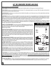
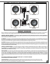
XLR CONNECTIONS
When connecting a balanced signal ensure it is wired as
per AES (Audio Engineering Society) specifications.
XLR
Hot (+) Pin 2
Cold (-) Pin 3
Ground Pin 1
2
HOT
SHIELD
COLD
3
1
1
COLD
3
2
SHIELD
HOT
SHIELD
COLD
HOT
KEY
HOT
COLD
GROUND
4
Numbers in this section refer to the numbered controls opposite