4 5
1201URX/Si Top Panel display and operation (continued)
Mode #2 (CH):
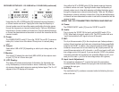
To change the channel/frequency within the selected group, press the MODE
switch a 2nd time. “CH” will be displayed. Using either the UP or DOWN
button [ ] the desired receiving channel/frequency combination can be set
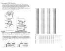
(the chart on page 3 shows the relationship). Tapping the button steps the
channel/frequency number one at a time while pressing and holding the but-
ton moves through the combinations rapidly. There are 188 different channel/
frequency combinations to choose from “Group” allows you to select all of the
combinations). Once the desired channel/frequency has been determined set
both the transmitter and receiver to match. When the receiver is turned OFF
the last channel/frequency chosen is stored in memory.
s
Mode #3 (SQ):
To change the squelch level, press the MODE switch for a third time. “SQ” will
show in the display. There are 3 settings to choose from:
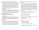
on on = RF mute ON - Tone mute ON (default)
on off = RF mute ON - Tone mute OFF
off off = RF mute OFF - Tone mute OFF
You can cycle through these with the UP/DOWN buttons. The squelch returns
to the default when the receiver is turned OFF.
Mode #4 (SQ Level):
There are four levels of Squelch to choose from:
0 =Default
3 = 3dB (RF) increase to the default
-6 = 6dB (RF) decrease to the default
-3 = 3dB (RF) decrease to the default
You can cycle through these with the UP/DOWN buttons.
See the discussion at the bottom of page 2 and the top of page 4 for informa-
tion concerning the other parts of the display.
RECEIVER SETUP/USE - 1201URX/AB or 1201URX/VM
As the RF signal from the transmitter gets stronger (or weaker) the number of
illuminated LCD segments in the display will change - with 3 segments being
the maximum and best. Similarly, the AF (audio level) segments will light from
1 to 3 segments as the audio gets stronger or weaker. In this case, the best
level is achieved as the display shows between 2 and 3 segments. If all 3
segments stay illuminated for a continued period of time it is likely that you
are over-driving the receiver’s input and you should reduce the transmitting
level by either moving the microphone further away from the sound source or
reducing the input gain on the transmitter.
THE 1201URX/Si
1201URX/Si Top panel display and operation:
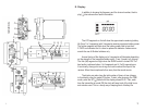
The MODE Switch [ ] performs 1 of 5 functions.
r
Initial MODE display:
The initial MODE shows the receiving band shown as Group, Channel and
Frequency. If there is no action taken with the MODE switch for 4 seconds
the display will return to the Initial Display. Pressing the MODE switch for one
second while showing the Initial Display will cause the currently set frequency
to be displayed.
Mode #1 (GR):
From the Initial Display, quickly pressing the MODE switch once displays the
Group Display. Pressing the UP or DOWN buttons will change the Group
Number. There are 7 Groups, 6 of which have the best selection of frequency
combinations when using multiple systems. Group 0 allows for choosing any
channel/frequency. The last Group is memorized when the receiver is turned
OFF. The chart on page 3 shows the Group vs Frequency combinations.
The 1201URX/Si receiver is specially designed to work with specic Pana-
sonic “Slot-In” or Ikegami “Uni-Slot” cameras. Once mounted in the camera,
the DB-25 connector on the bottom provides the receiver with power directly
from the camera’s power supply (battery) while delivering audio directly to the
camera’s audio input. Items A. [ ], C., D. [ ] and G. [ ] on pages 1 and 2
apply directly to the 1201URX/Si
j
p o


