


UPA224/UPA424
4
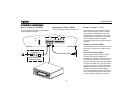
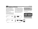
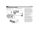
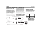
POWER WIRING
Power Indicator (POWER)
The power indicator provides a visual indication
that the amplifier is turned on.
Replacement Fuses (FUSE)
Use only blade-type ATO replacement fuses.
Power Terminal (+12V)
Connect the main power wire to the battery,
within 18 inches from the positive (+) battery
post, using an adequate size fuse or circuit
breaker capable of handling the current of the
selected power wire. A fuse or circuit breaker
must be installed to prevent a possible
electrical fire should the main power wire short
to ground.
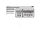
Remote Terminal (REM)
Connect the power antenna or amplifier turn-on
lead from the receiver to the amplifier remote
terminal.
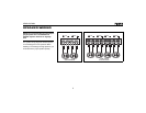
Ground Terminal (GND)
Make the ground lead as short as possible,
leaving enough length to complete the
installation and to allow for any service that may
be needed at a later date. To ensure a good
ground, scrape away any paint or undercoating
to expose bare metal. Use a "ring" terminal of
the proper gauge and an "outside star washer"
(between the chassis and ring terminal) when
making your ground connection. Although
you’ve scraped away the paint to expose bare
metal, the outside star washer will help to "bite
into" the chassis for a tight, secure ground.
Fuse or Circuit Breaker
Install as close to the
battery as possible.
B
B
L
E
T
A
A
A
D
F
R
S
U
B
-
W
SUB-W
M
O
N
O
MONO
A
S
/
P
S
AS/PS
D
I
S
P
DISP
LOC/DX
1
2
3
IN
T
4
5
6
B
A
N
D
S
C
A
N
E
Q
M
U
T
E
MODE
R
P
T
S
H
F
C
D
2
6
2
0
D
N
U
P
i
i
X
-BASS
C
H
A
N
G
E
R
4
0
W
A
T
T
S
x
4
JPTH
CD-R/RW
A
U
X
I
N
E
Q
i
4
A
U
X
AUX
CD
R
EC
EIVER
E
L
R
E
S
S
B
VO
L
SPEAKER
POWER
FUSE
+12V REM GND LCH RCH
POWER