


At this point, please determine the best way to route the
rest of the cable into your home to the SIRIUS home
receiver or SIRIUS Plug & Play system. If the included
cable is not long enough to reach your receiver,
you will have to purchase a TERK 50’ extension kit
(SIR-EXT50)-sold separately.
Electrical Specifications
Antenna
Frequency: 2320 to 2332.5 MHz
Gain: 1 dBic, 45˚-90˚ elevation
Bandwidth: 12.5 MHz
Impedance: 50 ohms
Polarization: LHCP (Circular)
LNA
Gain: 42 dB, typical
Noise Figure : 0.7 dB, typical
Current Drain: 160 mA, maximum
Mechanical Specifications
Antenna Dimensions:
Radome: 3 1/4” x 3 1/4"
Arm Length: 8”
Mounting bracket: 4 3/4" x 2 7/8”
Material: Xenoy and AES
Cable Type: RG-58 coaxial
Cable Length: 30 feet
Connectors Antenna: SMA
Connectors Cable: SMA and SMB
Mounting Hardware
Nuts and Washers: Stainless Steel
Screws and U-Bolts: Stainless Steel
Weight including cable: 1.75 lbs
Other Specifications
Temperature: -40 °F to +185 °F, operating
Quality and Performance Tests
SIRIUS Approved: Per Specification
RX000002H-010000
TERK Approved: Per Environmental
Specification TERK TRK-
10011-SIR6
SIR6
7
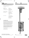
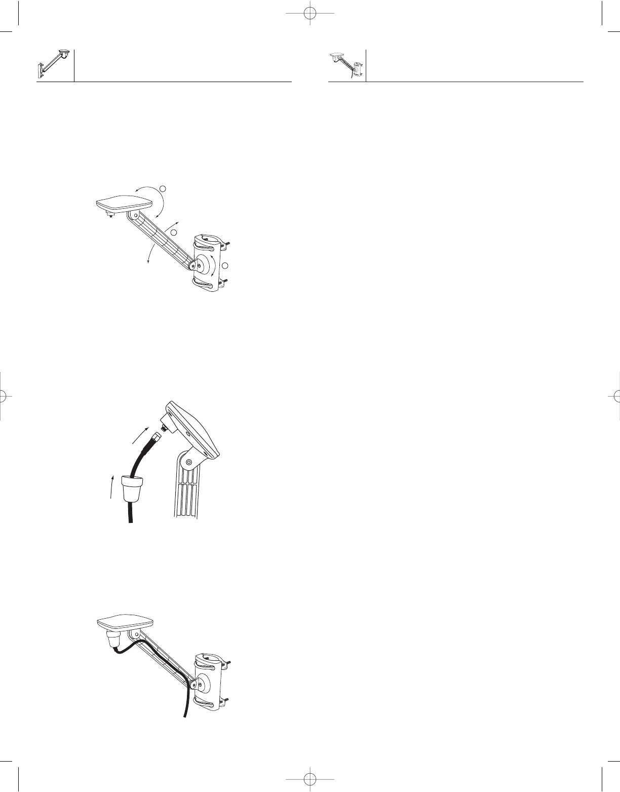
Adjustments
There are three areas of adjustments on the antenna,
antenna arm and mounting bracket. Please use these areas
to adjust the antenna so that it is level. You will have to
loosen the Phillips screws to rotate and adjust. Once the
adjustment has been made to the desired position,
tighten the Phillips screw. Be careful not to over tighten.
We recommend that you make the adjustments, if needed,
to each area in the order that is shown below.
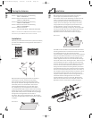
At this point you are ready to attach the cable.
The connectors at each end of the cable are different.
find the connector that has the threads on the inside,
then screw this connector onto the bottom of the
antenna as shown below. Screw the connector on
by hand as far as it can go. It is not necessary
to use any special tools for this.
Once the cable is secured onto the antenna, slide the
attached rubber bottom onto the antenna as shown.
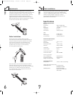
Uncoil the remaining cable. On one side of the mounting
bracket arm is a cable track with five cable clips.
For improved cable routing, snap the cable into the
cable clips as shown below.
SIR6
6
Cable Installation
3
2
1
Cable Installation
Specifications
T0365-SIR6-R1-OM.qxp 3/19/04 3:40 PM Page C6