


AS515
MTM In-Wall Cinema Speaker
Congratulations on your purchase of the AudioSource
AS515 MTM In-Wall Cinema Speaker. This product is
designed to reproduce the audio portion of your home
entertainment system with accuracy and detail that will
satisfy the most discriminating listener.
Please read this Installation Manual to ensure the proper
installation and performance of your AS515 speaker.
Preparing for your Installation
Gather the necessary tools for your installation.
You will need the following tools:
1) A Keyhole or Drywall Saw
2) A Phillips Screwdriver
3) Masking Tape
4) A Pencil
5) A Bubble or Laser Level
6) A Tape Measure
7) A Stud Finder (recommended)
8) Your AS515 Speaker
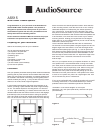
Placement
Plan your speaker placement carefully. Make certain that electrical,
plumbing and any other services will not interfere within the walls
where you plan to place your speakers. The AS515 speakers can
be mounted in the walls or in the ceiling, but are typically used in
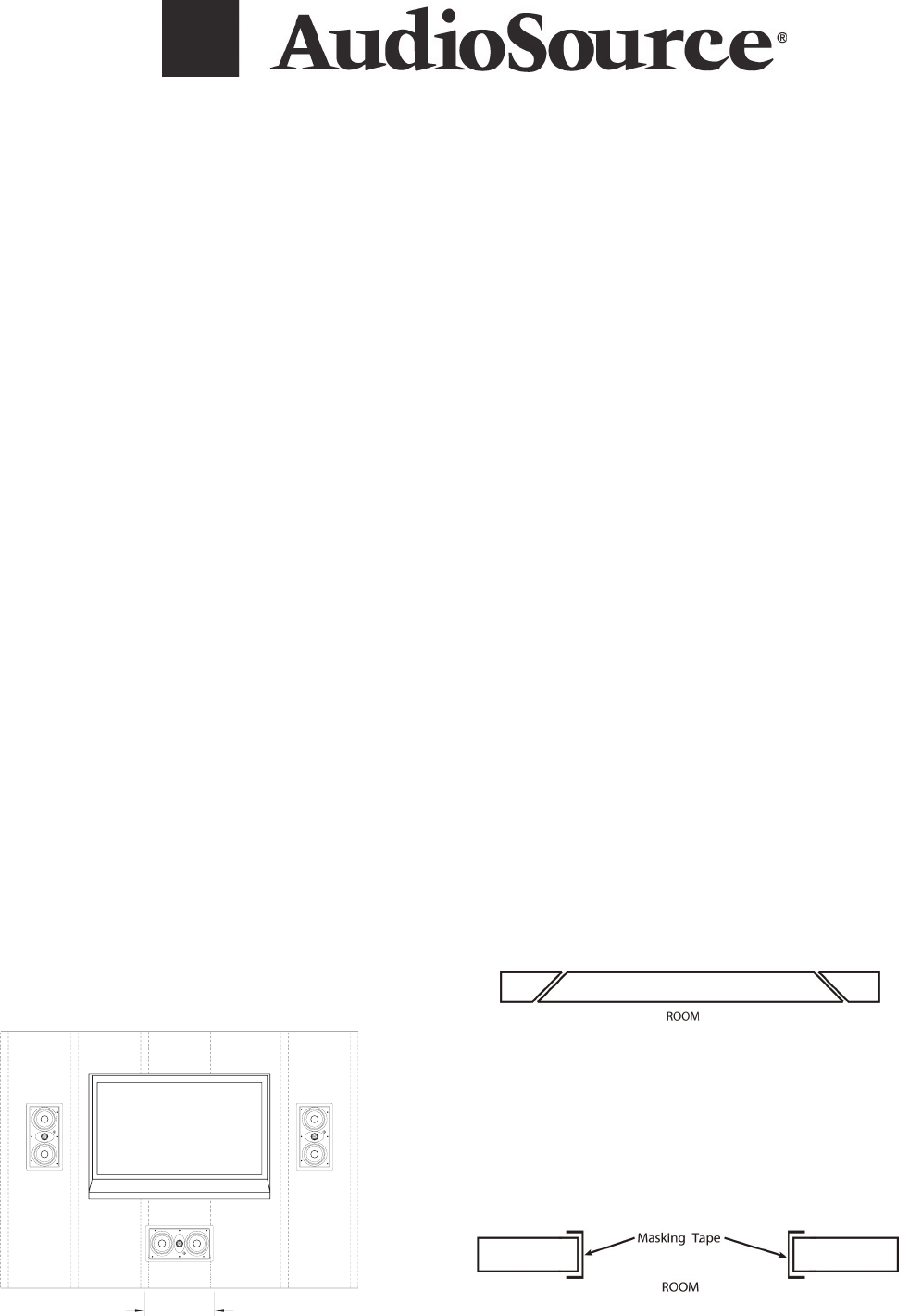
walls as a stereo pair (see fi g. 1). They are also used as a center
channel, or as a Left, Center, Right confi guration.
In most modern buildings the wall studs are positioned on 16”
centers, providing a space between the studs of approximately
14 3/8”. The AS515 requires a mounting hole 6 7/8” wide and
13 15/16” high. Additionally, you should allow an extra inch in all
directions behind the wall surface to allow room for the doglegs
that retain the frame to the wall surface to swing into position.
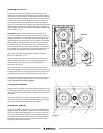
Use a stud fi nder to locate the vertical studs behind the wall sur-
face. You should now check for obstructions like cross bracing
above and below the desired speaker location. After selection
of the mounting location, mark the hole to be cut out. A handy
cardboard template is included with your AS515 speaker for
your convenience. Locate and level the template, then mark
with pencil on the wall surface. If you are unsure whether there
are obstructions behind the wall surface where the speakers are
to be mounted, cut a small hole in the center of your marked
mounting location. Holding your drywall saw at a 45 degree
angle (see Fig. 2) cut a square hole that you can use to fi nd any
obstructions, should they exist.
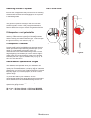
Once it has been determined that there are no obstructions,
cut the hole to mount the speaker using the drywall saw at a 90
degree angle to the wall surface. Cover the raw edges of the
wallboard with masking tape (see Fig. 3). This will prevent the
back pressure of the speaker from blowing loose gypsum dust
out and onto the painted wall surface after installation. Do not
allow the tape to extend more than 1/2” beyond the edge of the
hole into the room. The frame of the AS515 will cover and
hide the tape.
Next, run your speaker wire to your speaker locations. UL rated,
CL3 speaker wire is recommended when running wire inside
your walls (such as Phoenix Gold Innovative Home SS162W*).
In many areas it may be required by code. When running your
speaker wire you should avoid having the speaker wire run
parallel to the 110V power lines to avoid picking up hum and
interference from the power service. If the speaker wire needs
to cross a 110V power line, place it at a right angle to the 110V
line to minimize any hum or interference.
If you are uncomfortable with running the speaker wire yourself
in existing construction, it is recommended that you retain a
qualifi ed custom home installation specialist or electrician.
*Available in 3 convenient lengths: 50’ mini-spool
(M1650W), 100’ mini-spool (M16100W), and 250’ bulk spool
(SS162W/250).
Figure 2
Figure 3
Figure 1
16" WALL STUD SPACING
ati515