


AMP210 / AMP310
OWNER’S MANUAL
5
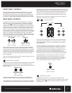
FRONT PANEL CONTROLS
The front panel power switch switches the AMP210/310 on or off. Red
LEDs behind the power button lens indicate power status. Whenever
the amplifier’s power switch is in the “ON” position and the amplifier is in
“Active” status the Signal/Clip LEDs are illuminated green. If the amplifier
is “ON” but in “Standby” status the Signal/Clip LEDs will illuminate orange.
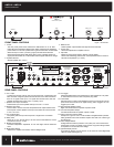
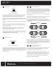
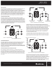
REAR PANEL CONTROLS
The AMP210/310 can be turned on and off independently via the power
switch on the front panel, by signal sensing, or remotely by a triggered
DC input. Switch
14
, located on the lower edge of the rear panel of the
amplifier, selects turn-on functions of the AMP210/310. If you would like to
control the unit’s power on / power off status manually from the front, place
the switch in the “Normal” position. If you would like to control the unit’s
power-on / power-off status by means of signal sensing, place the switch
in the “AUTO ON” position. If you would like to control the unit’s power-on /
power-off status by a DC remote trigger, place the switch in the “TRIGGER”
position, and connect the remote triggering cable from your triggering
device to the jack labeled “IN” next to the switch. When using 12V Trigger
or Auto On mode, the unit’s power button will be pushed in and the status
LEDs will be illuminated orange in standby condition.
Use a 3.5mm phone plug (in the “IN” connector) to make this connection:
the tip of the connector is (+) positive, and the sleeve of the connector is
(-) negative. A second jack in the same block is labeled “OUT”. This allows
for remote turn-on of other devices when the AMP210/310 is powered on.
Use the same polarity for the terminals of this plug. Please read the owner’s
manual for any devices you are attempting to connect in this manner to
ensure compatibility.
Note: The front panel power switch must be in the “ON” position for the 12V
triggers or “Auto ON” features to operate.
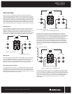
MASTER LEVEL CONTROLS
These level controls allow independent volume adjustment for each channel.
At the bottom left of the rear panel, there are 2 screwdriver adjustment
knobs which set the maximum level of the channel identified by the channel
designator below it.
The volume range is labeled Minimum to Maximum. Rotate the knob
clockwise to increase output, and counter-clockwise to decrease output.
These adjustments set the master level and if not configured at initial setup
of the AMP210/310 may adversely affect the performance of the amplifier.
Begin Master Level control setup by adjusting the front panel “Volume Trim”
to its fully clockwise position. Set the front panel “Balance Trim” to its center
detent position. Now adjust both the Left and Right Channel Master Level
controls to set a “Maximum” desired volume for the AMP210/310 in its
application, as well as setting an appropriate “Balance” from left to right.
Now use the front panel Volume and Balance Trim controls to make fine
adjustments to your setup in this application.
RCA INPUT/OUTPUT
There are 2 pairs of RCA inputs on the back panel of the AMP210/310.
These RCA inputs are labeled as “Line 1 IN” and “Line 2 IN”. They are
also designated with an “R” or an “L” as Right channel or Left channel
inputs respectively.
“Line 2 IN” should be used as the “primary” or normal input for various
line level sources that may be available to the amplifier. “Line 1 IN” is
a switching input that should be used when a second local source is
connected, and will take over as the selected input whenever a signal
with a minimum of 5mV of level is present. Whenever there is no
signal at the “Line 1 IN” RCAs, or a signal with less than 5mV level, the
input will revert back to the normal Line 2 input signal after preset delay.
An adjustable delay, of from 3 seconds to 15 seconds, can be set to
accommodate the nature of the source connected to the “Line 1 IN”
RCAs. As an example, if the “Line 1 IN” source was a CD Changer, the
delay could be adjusted to prevent switching back to the “Line 2 IN”
source while the changer moves from one disc to another.
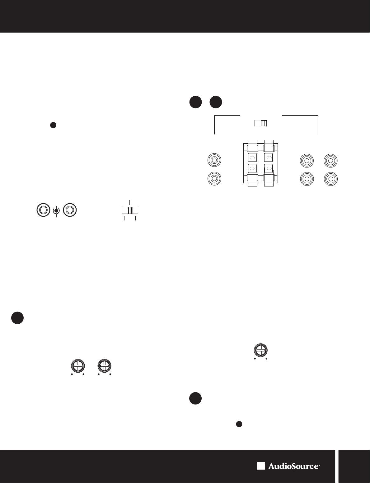
SPEAKER LEVEL INPUT
The AMP210/310 provides a pair of speaker level inputs for those
applications where either of the sources has only speaker level output signal
available. The switch routes the speaker level signal to either the Line 1
or Line 2 input.
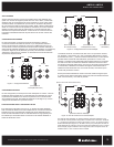
Figure 3. 12V Trigger Figure 4. Power Mode
Figu
re 5. Master Level
Figu
re 6. RCA Inputs
11
8
9&6
-
IN
OUT
12V Trigger
+
Trigger Normal
Auto On
Master Level
Min Max
Min Max
LR
IN
L
L
R
L
R
R
Speaker IN
IN OUT
Line 1 Line 2
Line 1 Line 2
+ +
- -
V
V
Delay
Time
3 Sec 15 Sec
Figure 7. Delay Time
7
13970 SW 72nd Ave. Portland, OR 97223 • 503.914.4688 • www.audiosource.net