


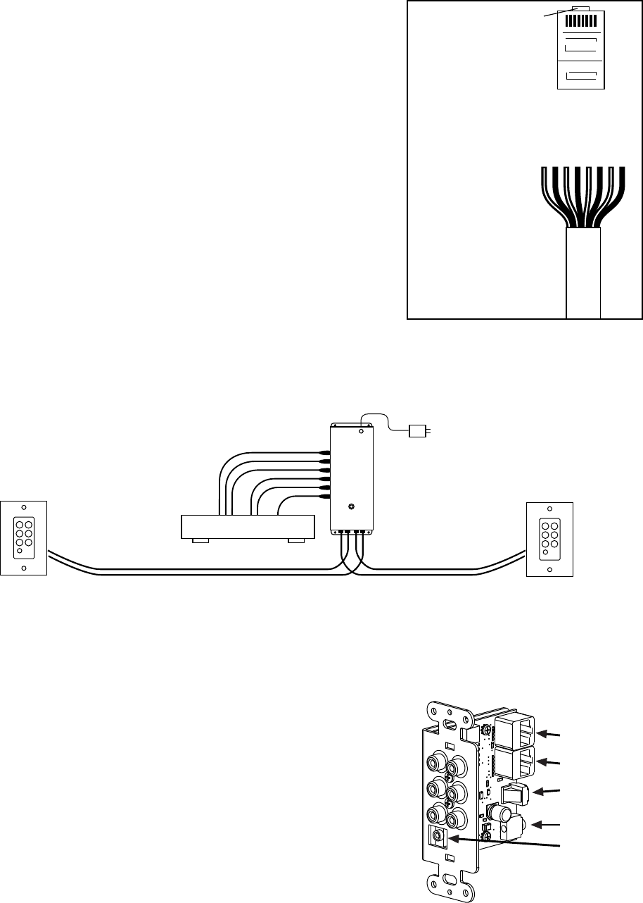
WHT / ORN
ORN
WHT / GRN
BLU
WHT / BLU
GRN
WHT / BRN
BRN
CATEGORY 5,
5e or 6 CABLE
Note: EIA 568A or B
standard may be used.
(B is pictured here.)
Make sure both ends are
terminated with the
Category 5
Connector
Termination
This diagram is
oriented with the
latch on the RJ45
connector facing
down.
RJ45
LATCH
Installing 9879 Wallplates
BE CERTAIN to connect the A cable to the A jack and the B cable to
the B jack or damage to the wallplate/receiver may occur. Adjust the
cable length compensation if the cable between the Driver and the
wallplate/receiver is over 100 feet long. Set the compensation at 1 for
cables 100-199 ft. long, and 2 for 200-299 ft. cables, etc. Do not
permanently mount the wallplate/receivers until after system testing.
Carefully connect the A and B cables to the Driver(s), power the source
components, TVs and AV receivers, and plug in 9871 power supplies
to test the system. Connect a TV to each wallplate/receiver location to
refine cable length compensation settings. Use the MINIMUM
compensation setting that still provides the best picture.
Ideally, Drivers should be located near the audio/video sources, but if
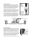
Cat 5 cable A
Cat 5 cable B
Cable Length
Compensation
9879 Wallplate/Receiver
Rear IR Jack
Cable Length
Compensation = 3
Cable Length
Compensation = 1
Cat 5 Cable Length = 320 ft. Cat 5 Cable Length = 180 ft.
RCA Cable Length =
Less than 199 ft.
Front IR Jack
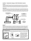
Installing the 9871 Driver
Mount the (first) 9871 Driver to any flat vertical or horizontal surface
using the screws provided. You may wish to leave space to add
9871 Drivers to expand output capacity. Connect component video
and all audio connections desired from the source equipment to the
inputs of the 9871. Use high quality, matched sets of component
video cables, and high quality RCA cables for audio. The IR bus
jacks are only used to connect 9871 modules together.
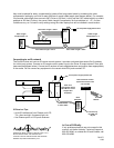
If installing more than one 9871 Driver, connect all the bus outputs
of the first Driver to the inputs of the next Driver using high quality
patch cables or Kit 46 (sold separately), which provides convenient
male to male connectors for a more compact installation. Connect
bus jacks for all channels whether or not they will be used.
Pull two cables to each wallplate location, preferably using a different
colored cable jacket for A and B cables. Install an RJ-45 termination
on each end of every Cat 5 cable, using EIA-568B pairing (pins 1-
2, 3-6, 4-5, 7-8). If possible, use EZ RJ-45 connectors. Check each
cable with a network cable tester – CONTINUITY TESTING IS NOT
ADEQUATE – the pairs must match the EIA-568B color code.
A
9871
Driver
B
AV Source
18-volt power supply PN 571-014