


INSTALLATION INSTRUCTIONS
INSTALLATION AND SET-UP FOR
SM8SUB70-B (CON’T)
Specifications are subject to change without notice
AtlasSound.com
1601 JACK MCKAY BOULEVARD ENNIS, TEXAS 75119 U.S.A. • TELEPHONE: (800) 876-3333 • FAX: (800) 765-3435
©2003 ATLAS SOUND LP 00803 ATS001614 RevA 8/03 PP
WARRANTY
All products manufactured by Atlas Sound are warranted to the original dealer/installer, industrial or com-
mercial purchaser to be free from defects in material and workmanship and to be in compliance with our
published specifications, if any. “This warranty shall extend from the date of purchase for a period of five
years on all Atlas Sound products except as follows: one year on electronics and control systems; one year
on replacement parts. Additionally, fuses and lamps carry no warranty.”
Atlas Sound will solely at its discretion, replace at no charge defective parts or products when the product
has been applied and used in accordance with our published operation and installation instructions. We will
not be responsible for defects caused by improper storage, misuse (including failure to provide reasonable
and necessary maintenance), accident, abnormal atmospheres, water immersion, lighting discharge, or mal-
functions when products have modified or operated in excess of rated power, altered, serviced or installed in
other than a workmanlike manner. The original sales invoice should be retained as evidence of purchase
under the terms of this warranty. All warranty returns must comply with our returns policy set forth below.
When products returned to Atlas Sound do not qualify for repair or replacement under our warranty, repairs
may be performed at prevailing costs for material and labor unless there is indeed a written request for an
estimate of repair costs before any non-warranty work is performed. In the event of replacement or upon
completion of repairs, return shipment will be made with the transport charges collect.
EXCEPT TO THE EXTENT THAT APPLICABLE LAW PREVENTS THE LIMITATION OF CONSEQUENTIAL DAM-
AGES FOR PERSONAL INJURY, ATLAS SOUND SHALL NOT BE LIABLE IN TORT OR CONTRACT FOR ANY
DIRECT, CONSEQUENTIAL OR INCIDENTAL LOSS OR DAMAGE ARISING OUT OF THE INSTALLATION, USE
OR INABILITY TO USE THE PRODUCTS. THE ABOVE WARRANTY IS IN LIEU OF ALL OTHER WARRANTIES
INCLUDING BUT NOT LIMITED TO WARRANTIES OF MERCHANTABILITY AND FITNESS FOR A PARTICU-
LAR PURPOSE.
Atlas Sound does not assume, or does it authorize any other person to assume or extend on its behalf, any
other warranty, obligation or liability. This warranty gives you specific legal rights and you may have other
rights that vary from state to state.
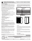
Please note that the input terminal cup includes corner threaded
inserts to accommodate standard four square electrical box
cover (RACO #753 or equivalent). The cover allows for conduit
connections directly to the input cup.
WIRE GAUGES (4 OHM OPERATION)
For very short distance speaker cable runs (less than 25') #16-
Gauge, stranded, twisted pair speaker cable may be used. For
speaker cable runs between 25' and 75', #14-Gauge, stranded,
twisted pair speaker cable is recommended. For speaker cable
runs greater than 75' #12-Gauge, stranded, twisted pair speaker
cable is necessary.
WIRE GAUGES (70.7V OPERATION)
Use 18/2 stranded twisted (plenum rated if necessary per local code)
for speaker cable runs up to 2000'. For distances over 2000' please
consult your cable supplier for suggested wire gauges.
OVERHEAD SUSPENSION INSTALLATION
Suspension or flying speaker systems requires training and
expertise. Improper rigging of a flying speaker may result in
injury, death, equipment damage, and legal liability.
Installation must be carried out by fully qualified installers, in
accordance with all the required safety codes and standards that
are applied at the place of installation. 5:1 design factor is a
generally accepted design standard, however, legal require-
ments for flying vary by municipality. Please consult you local
safety standards office before installing any product. We also
recommend that you thoroughly check any laws and bylaws
prior to installation.
If you lack the skills, training, and proper ancillary equipment to
fly a speaker system do not attempt to do so.
The Atlas Sound SM8SUB70-B system contains multiple
1
⁄4”-20
inserts to allow most any suspension angle conceivable. ONLY
LOAD RATED & CERTIFIED HARDWARE (EYEBOLTS &
CABLE) SHOULD BE USED IN THE INSTALLATION OF THIS
PRODUCT.
These products are available from:
ATM Group, Inc., 21000 S. Wilmington Avenue Carson, CA 90810
Tel (310) 834-5914 Fax (310) 834-3042
www.atmflyware.com
Loudspeakers flown in theatres, nightclubs, conference centers or
other places of work and entertainment must be provided with an
independent, correctly rated and securely attached secondary
safety – in addition to the principle suspension point(s). This sec-
ondary safety must prevent the loudspeaker from dropping more
than (6") should the principle suspension device fail.
SURFACE MOUNTING
The SM8CBKT-B is an Optional C-bracket for wall/surface mounting
of the SM8SUB70-B.
Whenever the loudspeaker is mounted to a
surface using the optional “C” bracket the installer must ensure
that the surface is capable of safely and securely supporting the
load. The hardware employed must be safely and securely
attached both to the loudspeaker and the surface in question,
using only the mounting holes. If you are unsure of the integrity of
the mounting surface please seek assistance from architects,
structural engineers or other specialists.
OMNIMOUNT™
Inserts are provided on the top, bottom and back of both models
to accommodate Omnimount™ brackets. Use the Omnimount™
30 series for the SM8SUB70-B.
STAND MOUNTING
The optional Atlas Sound SSA7 can be used with the top and bot-
tom cabinet inserts to facilitate stand mounting for portable use.
HEARING DAMAGE
CAUTION: These professional loudspeaker systems are capable
of generating very high sound pressure levels. Use care with
placement and operation to avoid exposure to excessive levels
that can cause permanent hearing damage.
OUTDOOR USE
The systems should not be flown or used in permanent outdoor
applications under any circumstances.
FUSE PROTECTION
Units are shipped with a 20A fuse installed. This high current fuse
functions as a through connection and offers no protection. If fuse
protection is desired please replace the 20A fuse with a 4A fuse
slow-blow type (AGC or 3AG type). Please note that for 70V opera-
tion the internal transformer with a maximum tap of 60 watts nullifies
the need for fuse protection.