


Specifications subject to change without notice
© 2002 Atlas Sound Printed in U.S.A. 000202 SL1-1192
1601 JACK MCKAY BLVD. / ENNIS, TEXAS 75119 U.S.A.
TELEPHONE: (800) 876-3333 / FAX (800) 765-3435
AtlasSound.com
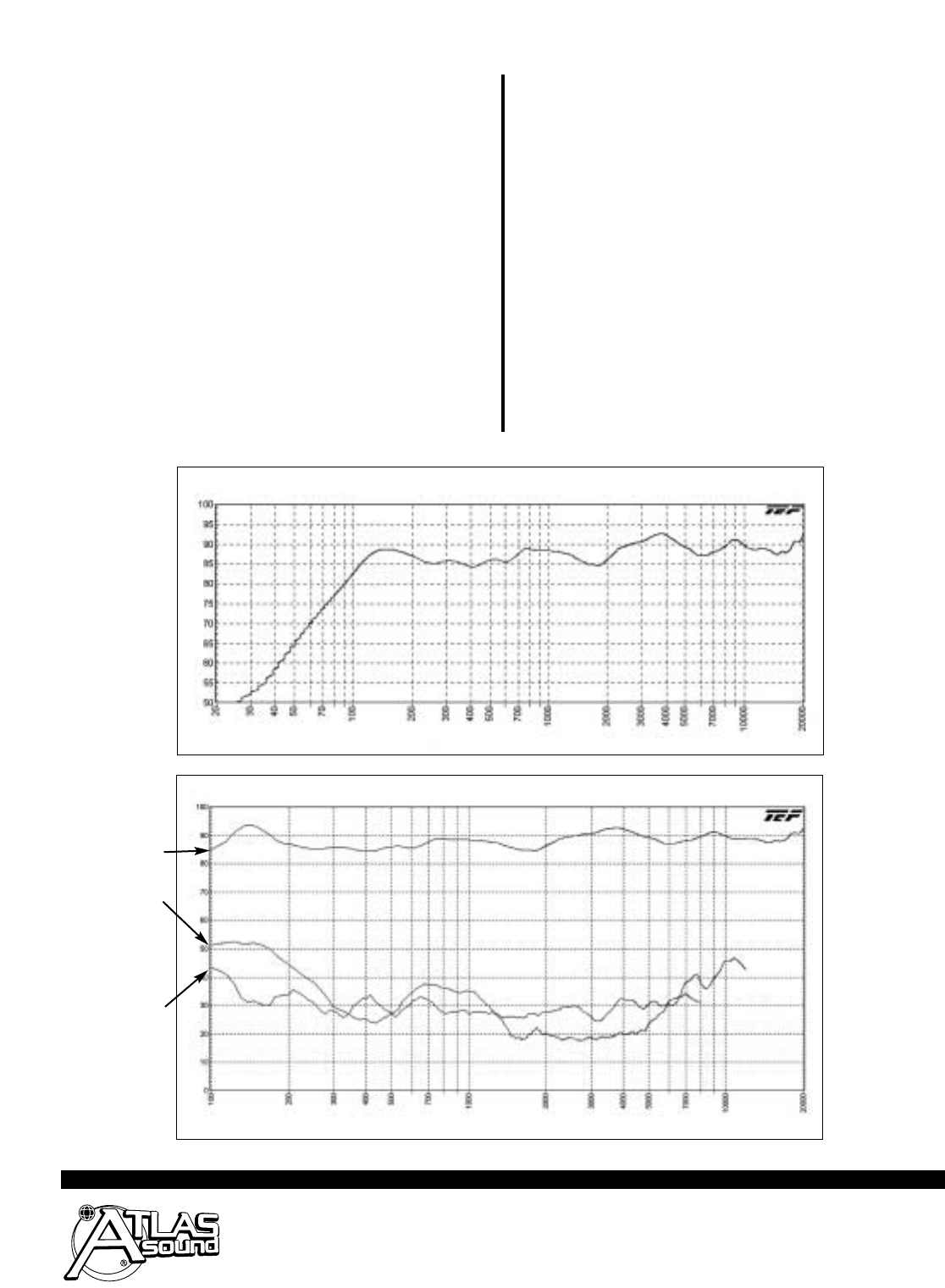
SM52T Frequency Response
(Transformer Bypassed)
SM52T Harmonic DIstortion
FREQUENCY (Hz)
FREQUENCY (Hz)
SPL in dB
SPL in dB
FUNDAMENTAL
3
RD
HARMONIC
2
ND
HARMONIC
Care should be taken to ensure that the chosen fixing point is strong
enough to support the SM52T. Care should also be taken to ensure
that the SM52T is not exposed to direct precipitation. A
5
⁄8"-27 threaded
hole is provided on the C-bracket to allow the SM52T series speaker
to be mounted on any Atlas Sound microphone stand for near-field live
sound applications. 2
3
⁄
8" OC brass inserts are also provided on the rear
of the SM52T to accommodate OMNIMOUNT™ 25 series brackets.
All inserts for mounting knobs are standard
1
⁄4"-20 to allow easy substi-
tution of off-the-shlelf vandal-proof torx head or "one-way" hardware.
Input connectors include a two pole barrier strip with wire capture
"caps" capable of accepting up to (2) #14AWG cable. .94, 1.9, 3.7,
7.5, 15, and 30 watt taps are screwdriver selectable via a sealed
switch located near the input section on the rear of the cabinet.
A tongue-in-groove cover with rubber wire exit grommet is provided to
protect the input connections and transformer switch assembly from
moisture. Systems are available in black or white and can be painted
to accommodate any architectural considerations.
ARCHITECT AND ENGINEER SPECIFICATIONS
The indoor/outdoor mini-loudspeaker system shall be Atlas Sound
Model __________ (SM52T-B or SM52T-W) or approved equal.
Assemblies shall consist of 2-way, woofer and tweeter, within
environment-resistant housings. Enclosure shall be constructed
of paintable UV-resistant, talc impregnated, polypropylene, injection
molded plastic finished in black (SM52T-B) or white (SM52T-W).
Each unit shall include a stamped, powder coated, aluminum grille
and removable C-shaped mounting bracket. All hardware inserts shall
be brass and threaded
1
⁄
4"-20. The 100-Watt RMS system shall have a
5
1
⁄4
" (133mm) woofer, constructed of reinforced polypropylene, and a
1" (25mm) FerroFluid tweeter. The dividing network crossover frequency
shall be 5000 Hz. The dividing network shall include protection circuits
for the high-frequency component. Each unit shall include an internally
mounted 30 watt 70.7V/100V line matching transformer for use in
distributed sound applications wattage taps shall be screwdriver selec-
table via a sealed switch located near the input section. Wattage taps
shall be .94, 1.9, 3.7, 7.5, 15, 30 @ 70.7V. The loudspeaker system
shall meet the following performance criteria: Power handling, 100 Watts
RMS (Transformer limited); Frequency response, ±3dB from 85 Hz to
20 kHz; Pressure sensitivity, 90dB SPL at one watt, 100 Hz to 10 kHz
measured at a distance of one meter on axis. Input connectors shall
include a two-pole barrier strip capable of accepting up to (2) #14AWG
cable. A tongue-in-groove cover with rubber wire exit grommet shall be
provided to protect the input connectors from corrosion. The unit shall
be 10
3
⁄16"(25.8cm) high, 6
7
⁄8" (17.5cm) wide, 5
7
⁄8" (14.85cm) deep.