


Specifications are subject to change without notice
AtlasSound.com
1601 JACK MCKAY BOULEVARD ENNIS, TEXAS 75119 U.S.A. • TELEPHONE: (800) 876-3333 • FAX: (800) 765-3435
©2006 ATLAS SOUND LP Printed in USA ATS002536 RevA 10/06 PP
OWNER'S MANUAL
EQM131 31 BAND GRAPHIC EQUALIZER
7
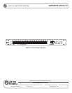
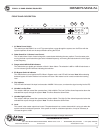
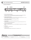
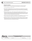
REAR PANEL DESCRIPTION
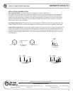
1. TRS 1⁄4" Input & Output Connections
Balanced signals can be accomplished by wiring the 1⁄4” as follows: Tip (+), Ring (–) & Sleeve (GND) plug
Unbalanced
1
⁄4" signals can be accomplished by connecting the Ring and Sleeve together.
2. XLR Input & Output Connections
Balanced signals can be accomplished by wiring the XLR Male and Female connectors as Pin 2 (+) , Pin 3 (–)
and Pin 1 (GND). For unbalanced signals, connect Pins 1 & 3 together.
3. RCA Input & Output Connectors
Unbalanced signals are only available when using the RCA connectors.
4. Ground Lift Switch
This switch breaks or makes the electrical connection between circuit ground and chassis ground. If hum is
audible, select the setting that eliminates the hum.
5. AC Mains Line Voltage select switch
Match the AC mains select switch to the AC source available.
Note: Make voltage selection prior to plugging in
the unit.
6. AC Mains Fuse
Only replace fuse with 500mA 250V fuse.
7. AC Mains Power cord
Plug unit into AC source.
Note: Make voltage selection prior to plugging in the unit.
1
1
3
4
5
7
2
2
6
3