


Specifications subject to change without notice
© 2001 Atlas Sound LP Printed in U.S.A. 000501 SL10-1549
1601 JACK MCKAY BLVD. / ENNIS, TEXAS 75119 U.S.A. / TELEPHONE: (800) 876-3333 / FAX (800) 765-3435
ARCHITECT & ENGINEER SPECIFICATIONS
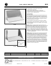
The 20" wide wall mount shelf shall be Atlas Sound Model
____________ (AS-120, AS-140) or approved equal. Shelf shall be
constructed of 16-gauge CRS, ___________ (AS-120: welded or AS-
140: three piece bolt together with hardware), and include four mount-
ing holes on 16" centers for stud mounting to a wall surface. Wire
access shall be provided by two 1
1
⁄2" holes on shelf bottom and one
1
1
⁄2
" hole on each side hanger. Weight capacity of the shelf shall
be______ (AS-120: 100 lbs., AS-140: 150 lbs.). The wall shelf shall
be finished in _________ epoxy. Model AS-120 shall include a
3
⁄8"
front return for equipment retention. Model AS-140 shall be formed on
all four sides and include welded hanger gussets for versatile installa-
tion above or below side panel/hanger supports.
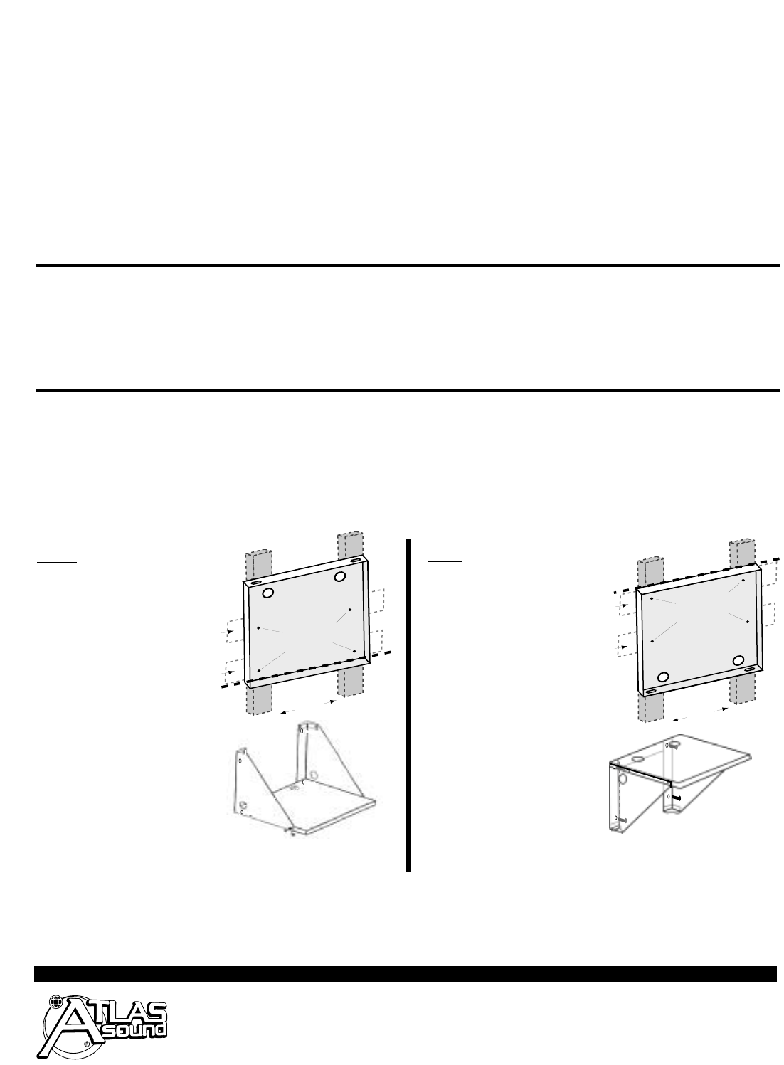
AS-140 ASSEMBLY AND MOUNTING INSTRUCTIONS
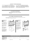
AS-120 MOUNTING REQUIREMENTS
Note: the mounting holes are on 16" centers. If your wall does
not have studs spaced 16" apart, install a solid cross support or
mounting plate.
Wiring Access holes
face DOWN
Level Line
Mark These
Four Holes
Shelf Mounts
to Wall Studs
Spaced 16"
Apart
Cross Supports or Mounting Plates May
Be Used to Span Studs Not on 16" Spacing
Wiring
Access
holes face
UP
Mark These
Four Holes
Level
Line
Level
Line
Shelf Mounts
to Wall Studs
Spaced 16"
Apart
Cross Supports or Mounting Plates May
Be Used to Span Studs Not on 16" Spacing
INSTALLATION FOR SHELF
BELO
W
SUPPORTS
1. Determine location on the
wall for the shelf top surface.
2. Add an additional
7
⁄8
" (for the
additional height of the shelf
bottom) and make a level line.
3. Indicate and drill the four
bracket holes using the tem-
plate on the shelf bottom as
indicated.
4. Bolt the hangers to shelf
bottom with supplied 4 qty.
10–32 x
1
⁄2" screws, nylon
washers, and nuts.
5. Mount the assembled shelf
to the wall using 4 screws or
lag bolts (by others). Note:
The bottom 2 bolts will go
through both the shelf bottom
and the side hangers.
INSTALLATION FOR SHELF
ABO
VE
SUPPORTS
1. Determine location on the
wall for the shelf top surface.
2. Indicate and drill the four
holes using the template of
the shelf top as indicated.
3. Bolt the hangers to shelf
top with supplied 4 qty.
10–32 x
1
⁄2" screws, nylon
washers, and nuts.
4. Mount the assembled shelf
to the wall using 4 screws or
lag bolts (by others). Note:
the top 2 bolts will go through
both the shelf top and the
side hangers).
Note: the mounting holes are on 16" centers. If your wall does not have studs spaced 16” apart, install a
solid cross support or mounting plate as shown below.
MTG. BOLTS (4)
MTG. BOLTS (4)