


Specifications are subject to change without notice
www.AtlasSound.com
1601 JACK MCKAY BOULEVARD ENNIS, TEXAS 75119 U.S.A. • TELEPHONE: (800) 876-3333 • FAX: (800) 765-3435
© 2003 ATLAS SOUND LP Printed in U.S.A. 00803 ATS000706 RevC 8/03 PN 416689
INSTALLATION INSTRUCTIONS
INSTALLATION MADE EASY
1. REMOVE BRACKET, END CAP AND HORN FROM CONTAINER.
2. DETERMINE MOUNTING REQUIREMENTS:
NOTE! It is the installer's responsibility to mount the product in a safe manner.
When selecting a mounting location, make sure that the location and mounting
method will support the weight of the loudspeaker. Additionally, take into con-
sideration other factors such as wind, vibration, snow/ice accumulation, etc. to
eliminate the possibility of injury or property damage.
WALL MOUNT
Attach base directly to wall via
(4) holes
provided in base using screws provided or
suitable strength fasteners.
STRAP OR CLAMP MOUNT TO A POLE OR BEAM
Attach base directly to pole or beam via a
1
⁄2"
hose clamp or suitable banding strap. A beam
clamp may also be utilized with the APX base.
Make sure that the strap, banding or clamp is
correct for the application environment.
SINGLE GANG, TWO GANG OR
4" SQ. E.O. BOX MOUNT
Using a box screw
(#6)
or a nail, align center
2 knock out holes
(4 on 2 gang) in base and
knock out holes with hammer. Pull speaker
wire through rubber grommet in base. Attach
base through 2 center knocked out holes
(4 outer holes on 2 gang box).
EXTERIOR BOX WITH FLEXIBLE CONDUIT
Using a hammer and a box screw
(#6) or a
nail, knock out holes in base. Knock out
1
⁄2"
K.O. in base plus the back cap with hammer
and screwdriver or pliers. Attach BX adapters
and flex conduit to base and backcap. Place
gasket on box
(not provided). Pull speaker wire
through box gasket, base and flex conduit.
FLUSH/BULKHEAD STYLE MOUNTING
Cutout size of the loudspeaker is 13
1
⁄8" x 8
5
⁄8"
K.O.'s are
1
⁄4" holes.
NOTE! In retrofit applications, if you are replacing Atlas
Sound AP Series speakers, you may use the existing AP
bracket for the APX Series. Simply unscrew wing nut on
the APX to remove base and mount to AP bracket.
(if color match AP base is desired, order XS8200601)
3. TO SET POWER TAPS, ROTATE
SWITCH WITH FLAT BLADE
SCREWDRIVER TO
DESIRED POWER OR
IMPEDANCE.
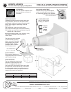
4. SLIDE LOUDSPEAKER ONTO BASE
SLEEVE UNTIL IT SNAP-LOCKS. INSERT
AND TIGHTEN BASE SLEEVE SCREW
TO DOUBLE LOCK SPEAKER TO BASE.
NOTE! To remove speaker from snap-lock-
base sleeve, first remove base sleeve
screw. Then insert screwdriver in opening
under sleeve and gently pry snap lock up to
remove base sleeve.
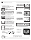
5. FEED HOOK UP WIRES
TO UNIT AND WRAPAROUND
CAP SCREWPOSTS
AND/OR THE WIRE BARRIER
BRACKET FOR STRAIN-RELIEF.
6. ATTACH WIRE TO SCREW TERMI-
NALS AND SECURE CAP WITH TWO
PARTIALLY CAPTIVE SCREWS.
THIS STEP "TRIPLE LOCKS" THE
LOUDSPEAKER TO THE BASE.
NOTE! For wiring adjustments, back-out the
right screw on the security cap more than
the left screw to provide swing-open access!
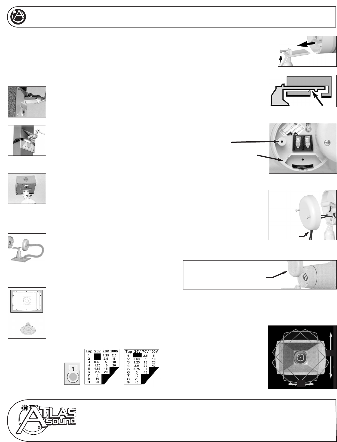
7. AIM HORN IN THE APPROPRIATE DIRECTION AND LOCK INTO
PLACE BY TIGHTENING WINGNUT ON BASE ASSEMBLY.
8. ROTATE BELL
(if needed)
Loosen the tip assembly in
horn bell by turning
1
⁄2 turn
counter clockwise, rotate bell
to position
(in 15˚ increments)
and lock back in place
by turning tip back
1
⁄2
turn clockwise.
WIRE SLOT
NOTE: that slot may
be enlarged using
needle-nosed pliers.
60˚
40˚