


Specifications subject to change without notice
© 2001 Atlas Sound LP Printed in U.S.A. 000501 SL2-1459
1601 JACK MCKAY BLVD. / ENNIS, TEXAS 75119 U.S.A. / TELEPHONE: (800) 876-3333 / FAX (800) 765-3435
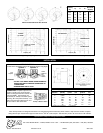
APF-15TU(C) Frequency Response
APF-15TU(C) (Harmonic Distortion - 1.5 watts @ 1 meter)
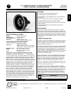
Polars Are Normalized To Zero On Axis
Fundamental
2nd Harmonic
3rd Harmonic
15 watts
@1 meter
1 watt @ 1 meter
MAGNITUDE (dB)
Frequency (Hz)
MAGNITUDE (dB)
Frequency (Hz)
* UL 3dB Increment Rating ** Do Not Use
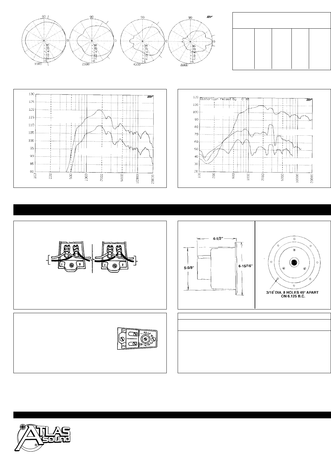
WIRING DIAGRAM
To conform with UL requirements,wires must be connected as shown in wiring diagram.
Speaker 1 Speaker 2
INSTALLATION
To Next
Speaker or
End
of Line
Resistor
CAUTION:
• DO NOT LOOP WIRES UNDER SCREW TERMINALS.
BREAK WIRE RUN TO PROVIDE SUPERVISION OF
CONNECTIONS
• MAXIMUM WIRE SIZE IS 18-GA.
From
Amplifier
Frequency
Lp Q Di
Beamwidth
(Hz) (Degrees)
1000 94.73 3.37 5.27 160
2000 91.37 7.30 8.63 95
4000 89.23 11.95 10.77 90
8000 83.54 44.29 16.46 25
Atlas Sound products are designed and tested in our well-equipped research laboratory which contains a fully anechoic chamber, complete
analog Bruel & Kjaer measurement equipment and Techron
®
TEF 20
®
audio analyzer. Atlas Sound is proud to be a beta site for TEF software.
APF-15TU(C) Vari-Tap
®
Control Connect Center Xfmr. Power Taps
Switch Impedance Watts
*dB
Watts
*dB
Position (Ohms) @ 25V
10 ft.
@ 70.7V
10 ft.
1 5,000 – – 1 93
2 2,500 – – 2 96
3 1,300 .48 90 .38 96
4 666 .94 90 7.5 99
5 333 1.8 93 15 102
6 89 7.5 99 X** X**
7 45 15 102 X** X**
CONNECTION: Amplifier output line con-
nection is made to the screw terminals
which are designed with wire retainers for
insured reliability. Input terminals are
numbered (#1 and #2) to maintain system
phasing. (#2 is the positive terminal). The
wide and narrow slots adjacent to #1 and
#2 are used for cable strain relief.
Vari-Tap
®
Selector Switch
_
+
+
_