


6
Model 102, 212 and 422 SB Powered Subwoofer
Connecting Your Subwoofer
Use the low-level (RCA jack) subwoofer line out of your surround sound
receiver/processor. Simply connect your subwoofer with a high quality
shielded cable as shown in the diagram on page 7. Please consult your
processor/receiver manual for further information.
WARNING:
To prevent risk of electrical shock or damage to your
equipment, always unplug all component AC cords before pro
-
ceeding with speaker and component connections! The last step in
wiring your system should be plugging in the AC cords!
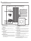
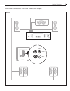
Subwoofer Line Out to Low Level In
Run an RCA cable from your receiver’s Sub Out jack to the L/Mono input
jack on the back of the subwoofer (Figure 3). If your receiver/processor
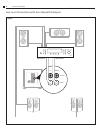
has stereo subwoofer outputs, connect these to both the L/Mono and R
jacks on the back of the subwoofer (Figure 4).
Using the Low Level Output
If desired, you can run a low level signal through the subwoofer and out
to another unit. This way you can add an additional subwoofer with mini
-
mal additional wiring. The signal that comes out of the output jacks is
identical to the input signal.
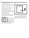
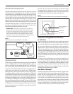
Power Connection
Connect the power cord to an AC
outlet only after making all other
connections to the subwoofer. This
will avoid any chance of accidentally
activating the subwoofer while wir
-
ing. Atlantic Technology does not
recommend plugging the subwoofer
into the switched outlet of an amplifier, preamplifier, or receiver. The
power demands of the subwoofer amplifier may exceed the power rating
of the switched outlet and may damage the equipment.
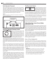
Figure 2
AC Connection
Your subwoofer is totally automatic in its operation. The automatic on/
off circuitry will only activate the subwoofer in the presence of an audio
signal from your system. After 7-10 minutes with no signal detected from
the rest of the system, the amplifier will shut itself off and go back into
standby mode. When the sub is in operating mode, the status LED will
glow green. The LED will glow amber in the Standby mode and power
consumption in this mode is negligible. Standby operation can be com
-
pletely bypassed by placing the standby switch on the rear panel to the
ON position.
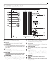
Connecting Your Subwoofer
110-120V 220-240V
OFF
AC INPU
T
50-60Hz 300W MAX
ON
FOR 110-120VAC, USE 3A L 250V FUSE
FOR 220-240VAC, USE 2A T 250V FUSE
STANDBYLOWPASS LOWPASSPHASE OUTPUTINPU
T
NORMAL NORMALOFF
ON INVERTBYPASS
80 120
14040
R
L/MONO
WARNING: TO REDUCE THE RISK OF FIRE OR ELECTRIC SHOCK
DO NOT EXPOSE THIS APPLIANCE TO RAIN OR MOISTURE.
AVIS: RISQUE DE CHOC ELECTRIQUE-NE PAS OUVRIR
DOUBLE INSULATION - WHEN SERVICING USE ONLY IDENTICAL REPLACEMENT PARTS
2001310
CAN/CSA STD.E60065
CERTIFIED TO
CONFORMS TO
UL STD.6500
AUTO
DESIGNED BY ATLANTIC TECHNOLOGY IN USA,
MANUFACTURED TO SPECIFICATION IN CHINA