


Instruction Manual
9
You can connect your speakers by using a variety of audio connectors such
as banana plugs (single or double), pin connectors, spade lugs, etc., or you
can:
1.
Remove ½" of insulation from each wire end.
2.
Twist the stranded wire together, keeping the two ends
separate.
3.
Place the appropriate wire through the appropriate
postholes in the connectors. These holes are revealed when
you loosen the connector’s capscrew.
4.
Screw down the capscrew tightly, but be careful not to over
tighten it.
5.
Check the tightness of the capscrews 24 hours after hookup
and occasionally after that, as they can loosen over time.
We recommend that you check your local electrical codes to make sure that
you are not using improper connectors.
It’s important to observe polarity while making speaker connections: red
(+) terminals on the amplifier to red (+) on the speaker, black (–) on the
amplifier to black (–) on the speaker. Look carefully at the wires you are
using and note that one of the conductors of each pair will typically be
identified by color, printing on the outer jacket, ridges on the outer jacket,
or a thread intertwined with the wire strands. By convention, the marked
wire is connected to the red (+) terminal.
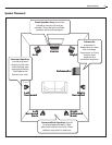
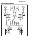
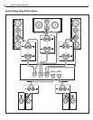
Whether your are connecting a complete system, or adding a single speaker
component to your present system, the wiring should look like one of the
system wiring diagrams on pages 7 and 8.
WARNING:
Before turning on the amplifier, be certain that no stray
wire strands are touching across any terminals as this might damage
your amplifier.
Finally, check the polarity of your front speakers by listening to some ste-
reo music with good bass content. If the sound seems “hollow”, unusually
spread out, or seem to have weak mid-bass, recheck your connections for
proper polarity and correct any out of phase connections, if necessary.
System Setup
Bass Management
Some older surround sound decoders and receivers offer a choice of “Nor-
mal” or “Wide-band” modes for the center channel speaker. The Model
8200e and 6200e C are designed to be used in the Normal mode. Addition-
ally, digital processing multi-channel systems provide a Bass Management
menu, which typically requires you to select between “Small” or “Large”
speakers during system set-up. Since these systems have been designed
to work with a dedicated subwoofer, please set all the speakers in Systems
6200e and 8200e to Small.
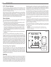
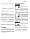
Operation of the Rear Panel Controls
on the LCR Speakers
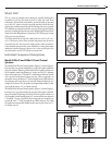
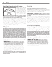
High Frequency Energy
This control
changes the tilt or roll-off slope of the
tweeter. It has been designed to help com-
pensate for different room acoustics. The
THX/ Average position is intended for
rooms with a reasonable combination of
reflective (hard) and absorptive (soft) sur-
faces. The Reverberant position is designed for rooms with an abundance
of reflective surfaces like hardwood or tile floors, glass walls, etc. It decreases
the high frequency output of the speaker to reduce excess HF energy that
builds up in live rooms. The Damped position brings the tweeter’s output
slightly above flat response to compensate for overly absorbent rooms with
lots of soft surfaces. Speakers in overly damped rooms can sound dead and
lifeless unless compensated.
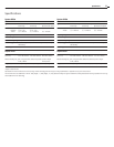
Location
This control “shelves up” the
upper midrange and high frequency energy
from the speaker in the position marked
Behind Screen. This is to compensate for
the reduction of these frequencies when
they are partially blocked by the materials
in front of them if the speakers are located
behind a perforated video screen or curtains. Of course, if you choose to
place the speakers behind curtains it is important to choose a material
that is as acoustically transparent as possible. Looking through the mate-
rial into the light can give you some indication of the material’s transpar-
ency in this regard. The more light and detail you can see, the better it will
be acoustically.
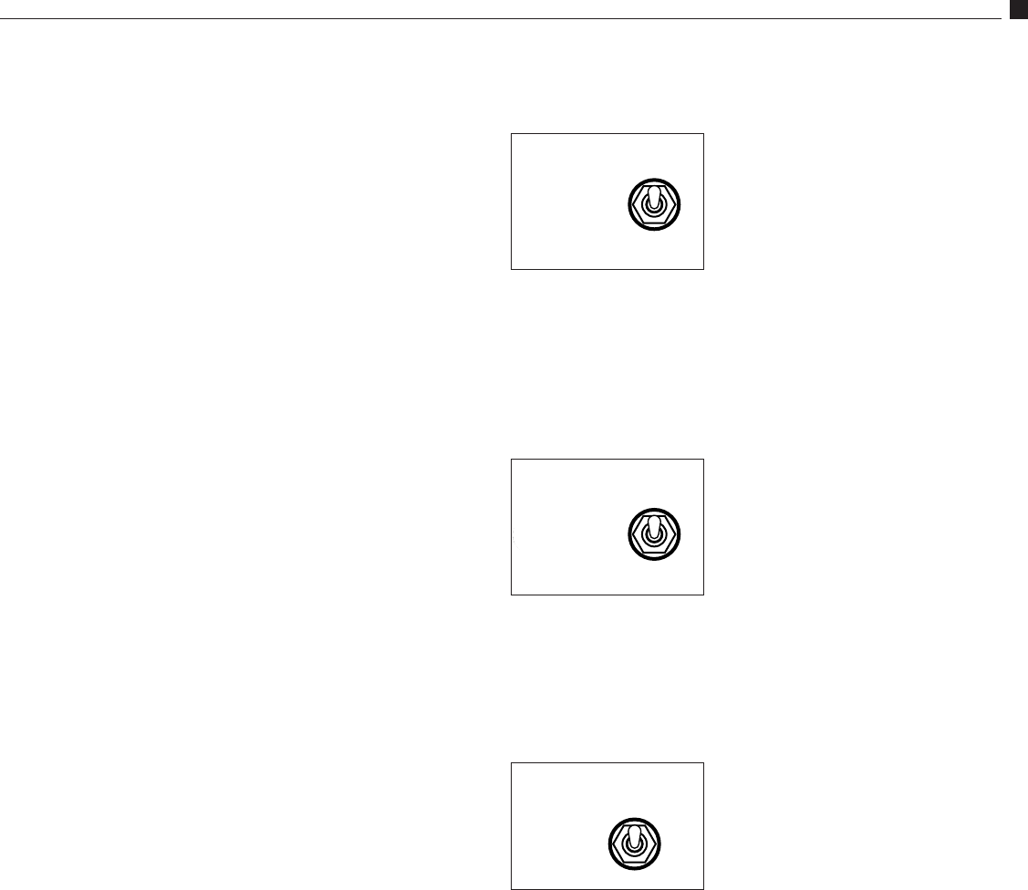
Boundary Compensation
Use this switch
to adjust the lower midrange output of
the speaker to compensate for the typical
sound colorations caused by placing the
speaker close to a TV screen or building it
into a wall unit or cabinet.
To set these controls, sit in the prime listening position and have someone
switch between the compensation choices, using well recorded dialogue or
musical instrument recordings. Choose whichever switch position sounds
most natural and real to you.
NOTE:
Although these controls have been designed to compen-
sate for various acoustic room anomalies, we recommend that you
try them to hear the difference that they make in the sound of the
system. For any number of reasons, you may decide that you prefer
them set in a particular manner inconsistent with your room’s acous-
tics, but sounds best to you. Experiment. It will be worth it.
HF ENERGY
– REVERBERANT
+ DAMPED ROOM
0 THX / AVERAGE
LOCATION
BEHIND SCREEN
THX / NORMAL
BOUNDARY
COMPENSATION
ON
THX / NORMAL
HF
LF
Gold Jumper
Links must be
removed if you
choose to bi-wire
the front channel
speakers.
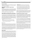
HF ENERGY
– REVERBERANT
+ DAMPED ROOM
0 THX / AVERAGE
LOCATION
BEHIND SCREEN
THX / NORMAL
BOUNDARY
COMPENSATION
ON
THX / NORMAL
HF
LF
Gold Jumper
Links must be
removed if you
choose to bi-wire
the front channel
speakers.
HF ENERGY
– REVERBERANT
+ DAMPED ROOM
0 THX / AVERAGE
LOCATION
BEHIND SCREEN
THX / NORMAL
BOUNDARY
COMPENSATION
ON
THX / NORMAL
HF
LF
Gold Jumper
Links must be
removed if you
choose to bi-wire
the front channel
speakers.
System Setup