


2
3
Atlantic Technology
®
Mounting Issues for System 5 LCR
(IWTS-5 LCR)
NOTE:
We always recommend a professional be involved in the installation of
InWall Theater System speakers, if at all possible.
The System 5 LCR speaker can be easily mounted in most any standard wall
material, from 1/2 to 1-1/2 inches thick. Its rotating wall clamps rmly x
it to the wall surface after the proper cutout has been made. Here are some
important precautions to take before mounting:
Keep the sides of the actual mounting hole at least 1-1/2 inches away from
beams or studs. The clamps require 3/4 of an inch to rotate, and a stud or
other obstruction that’s too close will stop them from properly doing their
job.
Wall cavity size will effect the bass and midrange performance of any in-wall
speaker. The System 5 LCR is designed to play optimally in a 0.5 to 1.0 cubic
foot space (measured before wall insulation is inserted). Cubic dimensions
can be determined by multiplying the length x width x height of the cavity.
A larger cavity won’t hurt, but a smaller one will de nitely impact the bass
and midrange response of the system.
Some of the sound from the speaker will transmit to the space on the other
side of the wall cavity. If this is a major concern, you can build a box within
the wall that provides the required cubic volume. The larger the volume, the
better the bass response will be, up to .75 cubic feet. Beyond this size there
will be no effective performance gain. Also please note that there is very little
room behind the drivers in a standard “2 x 4” wall cavity (there’s only 1/4
inch), so the back of any enclosure box must be made from relatively thin ma-
terials, yet it should not physically contact the back wall. Typically then, the
back wall material of your enclosure will be roughly 1/8 to 1/4 inch thick.
For optimum sound install the Atlantic Technology IWTS Foam Damping
Kit in the speaker cavity. If you don’t install this kit, at the very least line the
cavity with berglass wool (insulation), observing all the relevant precautions
and instructions from the insulation manufacturer. If you have built a back
box, you can use common berglass insulation or open cell foam rubber in
the enclosure. Be sure to push the insulation back from the drivers to ensure
that it doesn’t get into the moving cone area.
Ceiling Mounting
It is especially important when mounting the speaker in a ceiling that you
cover the back of the system with a berglass window screening (available
at any home center or hardware store) to keep insulation and other foreign
matter out of the assembly. You also should install safety wires from the rear
of the assembly to a secure mounting place, like adjacent beams or the oor
above, for added security. Should you be installing System 5 speakers in a
suspended ceiling, it is imperative to install safety wires from the speaker to
the support structure above, to ensure security under all conditions.
Installation of System 5 LCR in New
Construction
Atlantic Technology offers an optional Rough-in Frame Kit to ease installation
in new construction. Instructions for its use are included with this kit. The
kit’s model nomenclature is IN-NC-5
Installation of System 5 LCR in Existing
Construction
Removing and Installing the Grille
Remove the grille from the speaker using an awl or the point of a drywall
screw in a grille opening near one of the grille corners. Slowly pry the grille
out, being careful not to damage the speaker’s frame or its nish. Install the
grille by pressing it carefully into the appropriate opening in the frame as-
sembly. Since it’s designed to t snugly, please take your time and use care
when installing the grille.
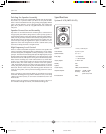
Cutting the Opening
After determining the best location for the speaker as outlined above, use the
enclosed template to cut the proper size hole (9-3/4” x 7-1/8”).
WARNING:
Exercise extreme care before making any wall cuts to ensure that you
will not cut through any wires, pipes, or other items that may be in the wall. You
may sometimes, but not always, be able to determine the approximate location of
wires and pipes by looking at the locations of nearby outlets and plumbing. But their
location or absence is never an assurance that there is not something within the
wall cavity.
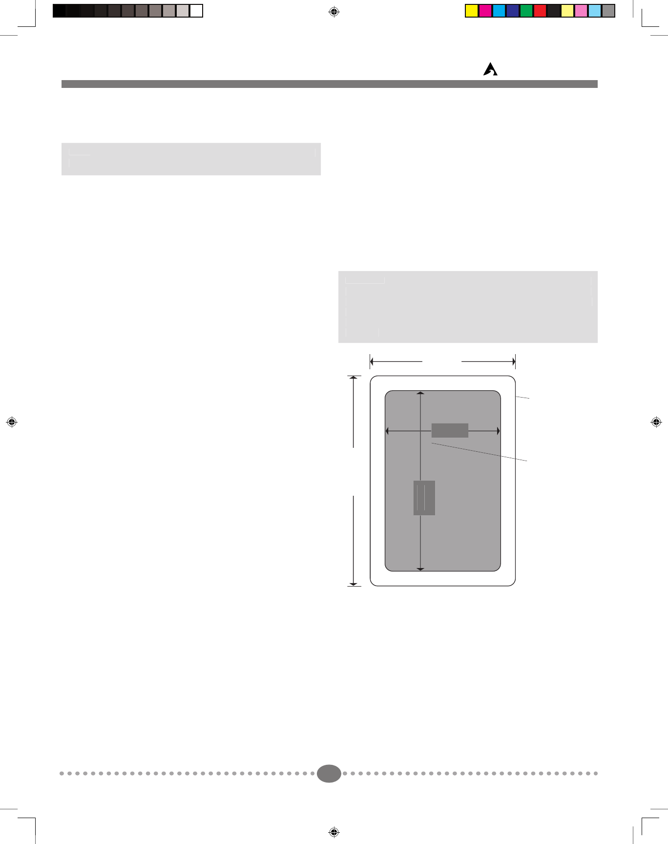
Speaker Cutout
Dimensions
Outside Speaker
Dimensions
8-1/2 in.
11-1/16 in.
7-1/8 in
9-3/4 in
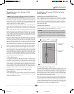
Installing the Mounting Frame
The clamping mechanism allows the wall material to range from 1/2 to 1-1/2
inches (12 to 38 mm) in thickness. There must be a minimum depth behind
the wall face of 3-5/8” (92 mm). As noted above, be sure to keep the edges of
the cutout at least 1.5 inch (37.5mm) away from any stud or obstruction, as
the rotating clamps will not operate properly if you don’t. The speaker baf e
(the part with the drivers mounted in it) is designed to mount into the white
frame, after the frame is mounted into the wall.
Insert the frame into the cutout and using a level or square carefully align it
so it is (or it appears) level. Tighten the mounting screws, which will cause the
attached clamps to rotate and position themselves properly behind the wall.
Continue to tighten until the frame is snug in the wall. You want the bezel
to conform to the wall board, and the frame not to rattle from the speaker’s
vibration but be very careful not to overtighten the screws.
System 5 Manual 2 5/31/02, 1:44 PM3