


Page - 8 Operator Manual – SRA Series Amplifiers
Copyright© 2010 – Ashly Audio Inc.
Operation
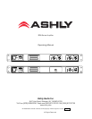
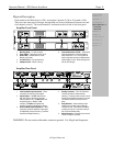
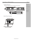
The amplifier’s On/Off Switch is a rocker-type switch located on the left side of the front
panel. Turning on the amplifier initiates start-up by activating the inrush current limiter.
When using the remote On/Off function, the main On/Off switch must remain in the On
position. See page 11 for more information on remote On/Off connections.
NOTE: The power switch does NOT isolate the appliance from mains. Make sure the mains
power socket or an alternative disconnect device is near by and easily accessible. When the
product is connected to mains, the line-filter and the input of the fuse are energized.
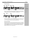
2 Channel (Stereo) Mode
In this mode, the amplifier’s channels operate fully independent of each other. Each signal
enters the unit and is amplified separately.
Bridged (Mono) Mode
In this mode, a single input is connected to channel 1 (or 1 & 3 in 4 channel models) and is
connected to the two output channels that have been “Bridged” together.
Each output channel processes the signal, but the polarity of channel 2 (and channel 4, in 4
channel models) is reversed. The (single) load is connected between the two positive
channel outputs. While the total output of the amplifier remains the same, both the
available output voltage and the minimum impedance that can be connected are doubled,
as compared with stereo operation.
Only Channel 1 (or 1 & 3) is active. A signal feeding Channel 2 (or 4) will have no effect
on the output.
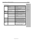
Important Safety
Instructions – 2
Introduction - 3
The SRA Series - 4
Physical Description - 5
Installation – 6
Operation – 8
2 Channel Mode
Bridged Mode
Troubleshooting - 9
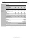
Spec Table - 10
Dimensions - 11
Warranty - 12