


Operating Manual - MFA-8000 and MFA-6000 Power Amplifier
8
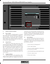
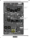
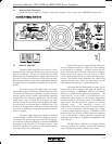
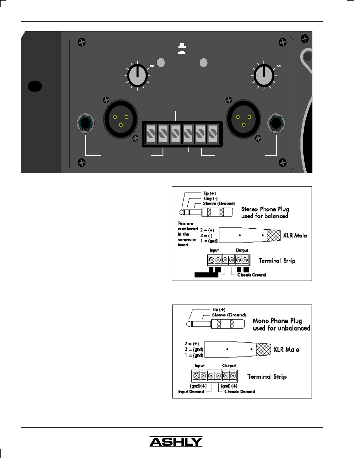
7. REAR PANEL FEATURES
7.1 Inputs
The standard input panel of the MFA series amps
is equipped with balanced 1/4" tip-ring-sleeve (TRS)
phone jacks, balanced XLR jacks, and balanced screw-
terminal inputs. The three types of connectors are inter-
nally wired in parallel and may be used with balanced or
unbalanced connections. The inputs are configured for
pin 2 hot, meaning that a positive voltage applied to pin 2
will result in a positive output voltage across the speaker
terminals. Pin 2 of the XLR jack is equivalent to the tip
of the 1/4" TRS jack. An optional input transformer is
available on all MFA amplifiers.
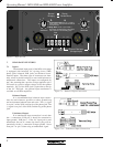
Balanced Inputs
It is recommended that balanced input connec-
tions be used whenever possible to reduce ground-loop
and environment-induced hum and noise. The (+) signal
is on pin 2 of the XLR, and the tip of the phone jack. The
(-) signal is on pin 3 of the XLR, and the ring of the phone
jack.
Unbalanced Inputs
If an unbalanced input connection is used, then
the (-) connection (XLR pin 3) should be connected to
input ground ( XLR pin 1). If the 1/4" input jack is used
unbalanced, the use of a mono (tip-sleeve) plug will au-
tomatically tie the (-) connection to input ground. Never
float pin 2 or pin 3 when using an unbalanced signal.
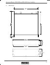
(-) (+) (-) (+)
Input
Ground
Chassis
Ground
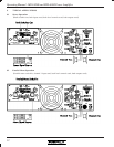
Normal
Bridging
Stereo
Parallel Mono
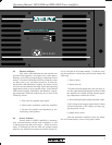
Parallel Mono Mode
ties Ch.1 and Ch.2
inputs together, using seperate level controls
for each channel.
Bridge Mode
uses Ch.1 input and Ch.1
level control, overriding stereo/mono switch.
Take output from two red binding posts.
Channel One Input
(Bridged Input)
Channel Two Input
Channel Two Channel One
0
-2
-6
-10
-20
-
0
-2
-6
-10
-20
-
Figure 7.1: Balanced Input Connections
Figure 7.1a: Unbalanced Input Connections
Figure 7: Input Section