


TROUBLESHOOTING CHART
AM/FM RADIOS
4
APPLICATION NOTES
AM/FM RECEPTION
Some boats have more than one
AM/FM radio.The best way to insure
good reception is to supply a
separate antenna for each radio.
Other options available to supply
adequate AM/FM reception to these
radios are listed below, along
some general information in
to radio reception.
"Y"ADAPTORS
The "Y" adaptors used to connect
one antenna to two radios will
compromise both AM and FM
reception.
AMPLIFIED AM/FM ANTENNA
A popular second antenna that
can be used is our AB-100 amplified
AM/FM antenna . It is small and
has a retractable mast that can be
mounted vertically or horizontally.
This antenna provides
reception , but the AM reception will
be compromised to some degree
because of the length
MAST LENGTH
AM/FM antennas compromise
AM reception by design . The
optimum mast length for FM is
approximately 30 inches which is
the standard for most automotive
antennas. The optimum mast length
for AM reception is over 100 inches
which is not practical for mobile
applications.
Special circuitry in electronic
tuned radios or AM trimmers in
mechanically tuned radios, make
up for some of this difference in
optimum mast length for AM
reception.
with
regards
good FM
of the mast.
ANTENNA CABLE
Increasing the antenna lead
cable ( adding extensions ) will
reduce sensitivity of AM with
electronic tuned radios.
GROUND PLANES
Ground planes are also
important when considering
antenna performance. Most
automotive antennas are
designed to be mounted on the
metal body of the vehicle.
The metal body reflects the
signal interference generated by
the vehicle's electrical system
while it also provides the ground for
the antenna lead shield. All this is
necessary in order to maintain a
good signal, especially AM.
FM RECEPTION
FM reception can be received
with a very limited antenna and
strong local FM stations can be
received without an antenna ,
depending on the circumstances.
CONCLUSION:
AM/FM reception is subject to
the choice of an antenna and it's
application. There can also be a
variety of methods used to supply
signal to both primary and
secondary radios , but AM
performance is the ultimate "test"
5
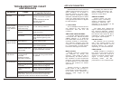
Symptom
Cause
Possible Solution
No Power
No 12VDC
Check circuit fuse at source
Check in-line fuse on power
lead
Power lead disconnected
Ground connection
disconnected
Power indicated;
no audio output
or very distorted
sound
No 12VDC to memory
lead(electronically
tuned units only)
Circuit fuse at source
In-line memory lead fuse
Speaker Output
shorted
Check continuity of speaker
leads to ground
Speaker out cross
channeled
Check for proper speaker wiring
Note: Radios have a sticker on
them explaining wiring color
code.
Only one channel
(right or left side)
Radio Balance
Check radio function
Speaker Disconnected
Check speaker connection at
radio and/or speaker
Speaker lead shorted
or grounded
Check speaker wiring continuity
to ground w/tester or meter
Popping in one or
both channels
Speaker wiring shorted
or positive lead
grounded
Speaker terminals
grounded or shorted
Leads from speaker cone to
terminal touching metal basket
or speaker
No AM Reception
Antenna disconnected
Connect Antenna
Antenna mast grounded
or shorted
Check antenna or substitute with
antenna known to be good
Antenna center lead
broken
Check antenna or substitute with
antenna known to be good
NOTE:Antenna leads can be tested with continuity or
multi-tester. Some may have electronic component
(capacitor) built in which not allow it to be tested.