


10
Run CAT5 wire from the keypad location to the GSZ67 location for each keypad or
run it from keypad to keypad location. Ideally home runs are used as they leave the
installation more “future proof” and reliable. Leave an extra 1 m or 3 feet on each
side to make it easier to work on. Add a RJ45 connector of the right type for the
CAT5 wire you have selected (not all CAT5 wires are the same) and crimp the
connector to the wire on each side. Plug the RJ45’s into the MR164 and correct
GSZ67 ports.
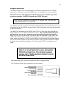
Note: MR164 keypad installer programming, see MR164
programming near the end of this manual.
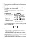
Infrared connections
On the rear of the GSZ67 there are seven infrared pass though ports. Each of the 1
through 6 corresponds to the keypad port next to them. For example IR port #3 is
the infrared output for keypads connected to KEYPAD #3. The infrared ALL is the
combination of all of the 6-keypad ports.
Using this method of infrared routing you can have six sources the same (like 6
identical AM/FM tuners) one for each zone and they can be controlled individually in
each room. Each port can control up to 8 devices using 4 of our optional IR34a
emitters and one IR55 connection block.
Each infrared port is a standard 3.5mm mono jack.
DATA IN and DATA OUT connections
On the rear of the GSZ67 amplifier there are two 3.5mm stereo jacks labeled DATA
IN and DATA OUT. These ports connect two or more GSZ67’s together so they can
share infrared commands and ALL commands (such as All Off)
When connecting two GSZ67’s together in one system you will need:
1. Up to fourteen (one for each active source) RCA patch cords
2. A 3.5mm stereo patch cord.
We do not recommend using “Y” adaptors in this case. Normally the two GSZ67’s are
near each other. If they are far apart then balancing baluns may be required to
eliminate stray noise on the lines.
The procedure to connect the two controller amplifiers is:
1. Connect the “Data Out” jack on GSZ67 #1 to the “Data In” jack on GSZ67
#2.using the 3.5mm stereo patch cord.
2. Connect all of the up to seven sources using short as possible good quality
RCA patch cords to GSZ67 #1 source inputs.
3. Connect GSZ67 #1 source outputs to GSZ67 #2 source inputs using good
quality, short as possible RCA patch cords.
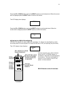
Page Inputs
On the rear of the GSZ67 there is a single page input on a stereo 3.5mm jack. This
is for connection of external paging equipment like our DC111 door chime generator.
The DC111 generates door chime sounds that are unique for the front, side and rear
doors. These paging sounds can be heard via the GSZ67 throughout the home even
if the GSZ67 is switched off or playing some other content.