


2.1 INPUT CONNECTIONS
Balanced XLR connection offers the highest transmission quality, particularly over long cable lengths,
because it rejects noise and hum pickup. Note that if an RCA plug is inserted into the RCA jack, that channel’s
XLR input is disabled. If your preamplifier does not have XLR outputs, use the Single-Ended RCA inputs.
Do not
use ‘RCA-compatible’ connectors that have a hollow center pin with a hole at the tip – inserting
them into the MCA amplifier’s RCA jacks can cause internal damage.
2.2 SPEAKER CONNECTIONS
Depending on the level of the input signal, the voltage at the outputs can be high enough to cause electric
shock – be sure that power is turned off when connecting or disconnecting anything. As well, be sure that
the speakers are rated for use with this amplifier – an overdriven speaker can pose a fire hazard.
Connect the red (+) connection on the speaker to the red (+) binding post on the appropriate amplifier
channel, and the black (–) connection on the speaker to the black (–) binding post on the same amplifier
channel, using cable that is insulated to handle the maximum output of the amplifier. Do not overtighten the
binding posts as this may cause damage. Each binding post accepts a connection from one speaker.
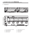
2.3 ON MODES
With the three-way switch located on the rear panel, you can set the way the amplifier is turned on and off.
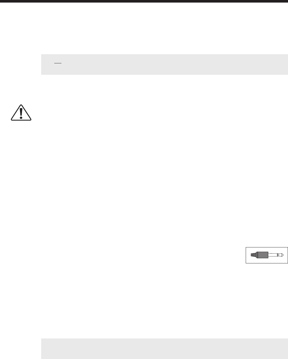
To use Trigger-On, connect a standard 3.5mm (.125”) mono mini plug cable between the amplifier and the
preamplifier or control component. Once all other connections are made, connect the power cord to the
amplifier and then the wall outlet. Some ‘clicks’ should be heard from relays inside the amplifier a few
seconds after power is turned on.
Manual-On:
When in this position, the amplifier is turned on/off via the power button on the front panel.
Trigger-On:
This feature allows the amplifier to be turned on or off remotely via the trigger. The
3.5mm (.125”) mini-jack INPUT receives power (5-24 volts, AC or DC) from an upstream
component or system controller. The same trigger signal can be linked to other
components through the OUTPUT. When using Trigger mode, leave the front power button in the ‘on’ position.
Auto-On:
This feature also eliminates the need to manually operate the power button. Auto-On turns the amplifier on
whenever it senses an input signal on any channel, and switches off 20 minutes after the input signal stops.
The power button on the front panel must be left ‘on’.
2-Color LED:
In Manual mode, the LED on the front panel is lit blue when the amplifier is on. In Auto or Trigger mode, the
LED is lit red to indicate standby mode, and blue to indicate operate mode.
Note: The amplifier is equipped with a thermal shut off feature. If it overheats, the affected channel will
remain off until the temperature falls below the shut off threshold.
2. CONNECTIONS AND OPERATION