


For full warranty information, refer to the AMX Instruction Manual(s) associated with your Product(s).
2/08
©2008 AMX. All rights reserved. AMX and the AMX logo are registered trademarks of AMX.
AMX reserves the right to alter specifications without notice at any time.
3000 RESEARCH DRIVE, RICHARDSON, TX 75082 • 800.222.0193 • fax 469.624.7153 • technical support 800.932.6993 • www.amx.com
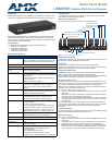
93-UDM-RX01 REV: A
Composite Input at Display Device
1. Attach the composite cable (normally yellow) to the CVBS connector on the
UDM-RX01.
2. Run the other end of the composite cable to the Composite connector (nor-
mally yellow) on the display device. Connect firmly.
3. If appropriate connect audio to the audio connectors on the UDM-RX01.
SVideo Input at Display Device
1. Attach the SVideo cable to the 4-pin S Video connector on the UDM-RX01.
2. Run the other end of the SVideo cable to the SVideo connector on the display
device. Connect firmly.
3. If appropriate connect audio to the audio connectors on the UDM-RX01.
Component Input at Display Device
1. Attach the Component cables (normally green, blue and red) to the Y (green),
Pb (blue) and Pr (red) connectors on the UDM-RX01.
2. Run the other end of the Component cable to the Component connectors (nor-
mally green, blue and red) on the display device. Connect firmly.
3. If appropriate connect audio to the audio connectors on the UDM-RX01.
Audio & Video Formats/Resolutions/Distance
Note: The maximum distances indicated above are not absolute, but are
recommended distances that have been tested to deliver video at the specified
resolutions, without significant signal degradation. In particular, lower resolutions
(640 x 480, 720 x 480 and 800 x 600) can often be delivered significantly further than
what is indicated in the table.
Refer to the UDM Hub’s Operation/Reference Guide for additional details on
maximum cable distances.
Video Compensation
Video at the Receive end can be compensated using three main methods;
• Using the UDM-Hub’s WebConsole
• Using the UDM-RC02 Multi-Format IR Remote Control
• Using a hyper terminal session via the serial connector on the UDM-RX01
(especially effective setup method when using long runs)
Connecting an External IR Receiver Module
If passthrough mode (where a device such as a DVD or VCR can be controlled via a
remote control) is required then an IR03 External IR Receiver Module will be needed
to pick up IR controls from the remote control.
Additionally, if the UDM-RX01 is to be compensated via a remote control, then an IR
Receiver Module is also needed.
Connecting the UDM-RX01 Receiver to the UDM Hub
The RJ45 port on the front panel of the UDM Hub labelled “UDM” supports one
UDM-RX01 Receiver. The UDM-RX01 is then be connected to a display device.
1. Connect a standard Cat5/6 Ethernet cable to the RJ45 port labelled UDM on
the front panel of the UDM hub.
2. Connect the other end of the Ethernet cable to the RJ45 port labelled UDM
Hub on the rear panel of the UDM-RX01.
Note: Ensure the port the UDM-RX01 is attached to is configured correctly within the
Status option of the WebConsole (for example, if a UDM-RX01 is connected to the
Hub, ensure the port in the Status option is configured likewise.
UDM HUB Port LEDs
2 LEDs are visible at the UDM Hub port (on the UDM-RX01) when the UDM hub is
switched on:
• Green – Connection to UDM-0102 (if Cat 5 removed, LED switches off).
• Amber – Power (as well as comms if uploading protocols etc. the Amber LED
may flicker).
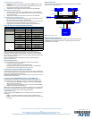
System Overview
FIG. 3 provides a basic system diagram representing a UDM Hub, UDM-RX01
Receiver, and connected devices:
Additional Documentation
Refer to the relevant UDM Hub Operation/Reference Guide (available online at
www.amx.com) for detailed information on configuring the UDM Hub, UDM
receivers and source devices.
Audio & Video Formats/Resolutions/Distance
Class Format Name Distance
Composite 720x480 NTSC 300 m / 1000’
720x756 PAL 300 m / 1000’
Component 720x480 480p 300 m / 1000’
720x756 576p 300 m / 1000’
1280x720 720p 200 m / 650’
1920x1080 1080i 150 m / 500’
1920x1080 1080p 120 m / 400’
VGA 640x480 VGA 200 m / 650’
800x600 SVGA 200 m / 650’
1024x768 XGA 200 m / 650’
1280x1024 SXGA 150 m / 500’
1600x1200 UXGA 120 m / 400’
FIG. 3 UDM System Diagram
DVD DSS
UDM Hub
UDM Receiver
Display
Ethernet
(network
Cat5
Video Out
Video In
Audio Out
Audio In
Video In Audio In
Video Out
Audio Out
Video Out
Video In
Audio Out
Audio In