


AMX Corporation reserves the right to alter specifications without notice at any time.
For full warranty information, refer to the AMX Instruction Manual(s) associated with your Product(s).
042-004-2747 6/05 ©2005
AMX Corporation. All rights reserved. The AMX logo is a trademark of AMX Corporation. AMX reserves the right to alter specifications without notice at any time.
3000 RESEARCH DRIVE, RICHARDSON, TX 75082 • 800.222.0913 • fax 469.624.7153 • technical support 800.932.6993 • www.amx.com
9
3-0456-10
REV: B
Preparing Captive Wires
You will need a wire stripper and a flat-blade screwdriver to prepare the
captive wires:
1. Strip 0.25 inch (6.35 mm) of wire insulation off all wires.
2. Insert each wire into the appropriate opening on the connector
according to the wiring diagrams in this section.
3. Turn the flat-head screws clockwise to secure the wire in the
connector.
Note: Do not over-torque the screw. Doing so can bend the seating
pin.
Wiring Guidelines
The AXD-IR+ requires 12 VDC power to operate properly. The power is
supplied by the AMX system's AXlink cable. The maximum wiring distance
between the Central Controller and the receiver is determined by power
consumption, supplied voltage, and the wire gauge used for the cable.
The following table lists wire sizes and the maximum lengths allowable
between the receiver and the Central Controller. The maximum wiring
lengths are based on a minimum of 13.5 volts available at the Central
Controller's power supply.
If you install the unit farther from the Central Controller than
recommended in this table, connect an external 12 VDC power supply, as
shown in the following wiring diagrams.
Connection and Wiring
Wiring the AXD-IR+ or the AXR-IRSM+ to AXlink
Install the AXlink data/power bus wiring as shown in FIG. 6.
Using the AXlink Connector with an External 12 VDC Power Supply
Use a 12 VDC power supply when the distance between the Central
Controller and the sensors or receivers exceeds the limits described in the
Wiring Specifications table above. Make sure to connect only the GND
wire on the AXlink connector when using a 12 VDC power supply (FIG. 7).
Note: Do not connect the PWR wire to the AXlink connector's PWR
(+) terminal on the Central Controller's side.
Checking IR Data Status
Locate the red IR Data LED on the front of the unit. Point the system's
AMX transmitter towards the sensor and press a button. The IR Data LED
lights when the unit receives data.
If the IR Data LED on the unit does not light:
• Verify that the transmit LED on the transmitter lights when you press
a button.
• Check the wiring to the unit.
• Verify that the transmitter frequency is properly configured.
Checking AXlink Status
The AXlink LED lights to indicate AXlink power/data status as follows:
If the LED is on and not flashing, disconnect the AXlink connector and
recheck all AXlink connections. Then, reconnect the AXlink connector to
the panel and verify the LED is flashing once per second.
Mounting the AXD-IR+
1. For wall or podium mounting (FIG. 8), AMX recommends mounting
the AXD-IR+ in a standard 1-gang wallbox with a minimum internal
clearance of 1 3/4" (W) x 2 5/8" (H) x 1 5/8" (D).
2. Gently remove the bezel from the wallplate.
3. Place the panel in the wallbox and align the screw holes with the
mounting holes on the panel.
4. Turn the unit over and locate the AXlink connector.
a. Connect the unit to AXlink data/power bus.
b. Check the AXlink LED (should blink once per second).
5. Fasten the panel to the wallbox using the screws supplied with the
panel.
6. Snap the wallplate back on the bezel.
Wiring Specifications @ 35 mA
Maximum Wiring Length
Wire Size Distance
18 AWG 3000 feet (914.40 m)
20 AWG 2121.64 feet (646.68 m)
22 AWG 1,322.75 feet (403.17 m)
24 AWG 833.80 feet (254.14 m)
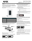
FIG. 6 AXlink wiring
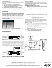
FIG. 7 AXlink wiring with an external 12 VDC power supply
1
2
3
4
1
2
3
4
AXlink connector
on the AXD-IR+
Central
Controller
GND
AXM
AXP
PWR
GND
AXM
AXP
PWR
1
2
3
4
1
2
3
4
AXlink connector
on the AXD-IR+
Central
Controller
GND
AXM
AXP
PWR
GND
AXM
AXP
PWR
12 VDC
Power
Supply
PWR
GND
• 1 blink per second Indicates power is active and AXlink communication is working.
• 2 blinks per second
Indicates the devices specified in the Master program do not match the
devices found.
• 3 blinks per second Indicates AXlink communication error.
• Full On
Indicates the following conditions:
• There is no AXlink control or activity, but power is On.
• The Axcess program is not loaded.
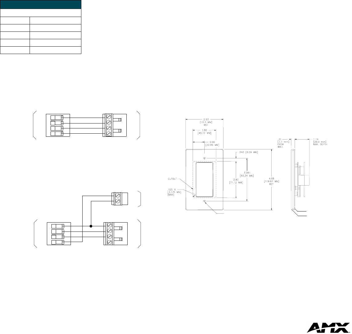
FIG. 8 AXD-IR+ Mounting Dimensions
Install unit using supplied #6-32
machine screws at these locations
wall plate
bezel