


Quick Start Guide
AXD-IR+ WallMount Remote IR Receiver
Overview
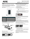
The AXD-IR+ (FIG. 1) is a remote IR receiver for use with both AMX
Axcess/NetLinx Central Controllers and operates via the AXlink bus to
remotely control AXlink devices. The AXD-IR+ is in a UniMount wall panel
that fits into most US-style single-gang enclosures. The AXD-IR+ works
with AMX 38 kHz or 455 kHz IR transmitters.
Note: The AXR-IRSM+ swivel-mount version is also available for wall or
ceiling installations:
Wiring and Installation
Set the receive frequency, AXlink device number and IR validation level
before installing the AXD-IR+. FIG. 2 illustrates the location of key
components on the AXD-IR+ circuit board.
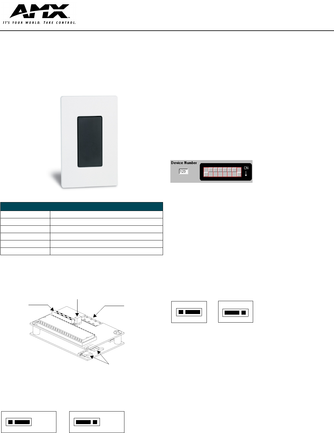
Setting the Receive Frequency
Use the set of jumper pins on the corner of the circuit board to set the
receive frequency. FIG. 3 illustrates the configuration of the jumpers..
Note: The unit will not operate with one set of pins configured for
38 kHz and the other set of pins configured for 455 kHz.
• To receive 455 kHz (default setting), position both jumpers on pins
1 and 2 (away from the edge of the circuit boards).
• To receive 38 kHz, position both jumpers on pins 2 and 3 (near the
edge of the circuit boards).
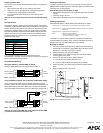
Setting the AXlink Device Number
1. Locate the 8-position Device DIP switch (FIG. 2).
2. Set the DIP switch according to the DIP switch values shown below.
The device number is set by the total value of DIP switch positions that
are ON (down). The Axcess software program in your system typically
uses device numbers 128 through 255 for the panels.
As an example, the DIP switch in FIG. 4 defines device number 129
(1+128=129).
Note: If you later change the device number, remove and reconnect
the AXlink connector to enter the new device number into memory.
Sensor IR Validation Level
The IR validation level is set on the receiving device (such as an
AXC-RCVI).
Setting the IR Validation Level
An IR transmitter must send repetitions of data for the receiver to accept it
as valid data. In some installations, a light wall color or other physical
condition may interfere with the sensor's or receiver's ability to sense the
transmitted signal. The signal may reflect or bounce and become distorted.
The receivers can be set to use either two or three repetitions of sequential
signals to validate and accept the signal data.
Perform the following steps to set the receiver's IR level.
1. Locate the IR jumper pins (J1) (FIG. 5) on the circuit board (FIG. 2).
2. Position the IR validation jumper (FIG. 5) to select the number of valid
IR data repetitions to be accepted:
• Position the jumper at 2 to have the unit validate 2 sequential signals.
• Position the jumper at 3 to have the unit validate 3 sequential signals.
Wiring the IR Sensors and Receivers
The AXD-IR+ uses a 4-pin AXlink connector for power and data. If the
distance between the receiver and Central Controller exceeds power
consumption limits, you can connect a local 12 VDC power supply to the
AXlink connector.
FIG. 1
AXD-IR+ UniMount IR receiver
AXD-IR+ Specifications
Dimensions (HWD): 4.68" x 2.93" x 1.44" (118.87 mm x 74.42 mm x 36.58 mm)
Available Colors: White (FG456-10) and Black (FG456-11)
Receive Frequencies: 38 / 455 kHz (user-selectable)
Mounting: Mounts into most US-style single-gang enclosures.
Weight: 7.8 oz. (218.4 g)
Power Consumption: 35 mA
FIG. 2 Location of key components on the AXD-IR+ circuit board
FIG. 3 Receive frequency jumper settings
AXlink Device
IR Validation
AXlink
DIP Switch
Jumper Pins
Connector
Receive Frequency
Jumper Pins
8-position
IR SNSR
38/455
kHz
Setting for 455 kHz
IR SNSR
38/455
kHz
Setting for 38 kHz
Switch 1234 5 6 7 8
Value 1 2 4 8 16 32 64 128
FIG. 4
Example Device DIP Switch set to 129
FIG. 5 IR validation jumper pin settings
Setting for 2 validations Setting for 3 validations
23
23
J1
J1