


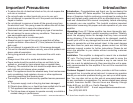
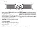
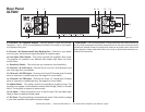
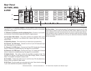
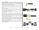
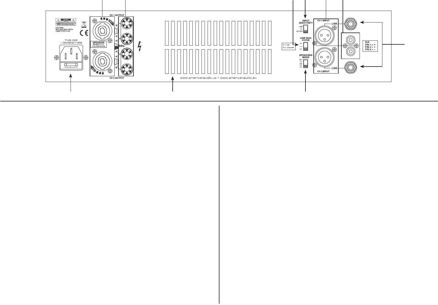
Rear Panel
XLT900
Figure 2
8
17 15
121110
9 13
14
©American Audio® - www.americanaudio.us - XLT Series Power Amplifier User Manual Page 6
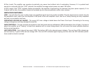
8. Channels 1 & 2 Speakon Outputs - Optional speaker output connections.
Use pins 1+ and 1- of this 4-pole Speakon connector to connect to your speak-
er’s Speakon input jack.
9. Channel 1 & 2 Output Jack/5 way Binding Post - Connect to your speak-
er’s input jack. Red is positive signal and Black is negative signal.
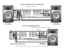
10. Low Pass Filter Switch - This switch controls the amplier’s lter mode.
The amplier can operate in two dierent lter modes; High Pass, Low Pass,
and By-Pass.
11. Sensitivity Switch - This switch lets you choose the input sensitivity.
12. Channel 1 & 2 XLR Input - Channel one & two 3-pin XLR balanced input
jack. See page 9 for more details.
13. Channel 1 & 2 RCA Input - Channel one & two RCA female jacks. Excepts
either a balanced or unbalanced plug. See page 9 for more details.
14. Channel 1 & 2 TRS Input - Channel one & two 1/4” female jacks. Excepts
either a balanced or unbalanced plug. See page 9 for more details.
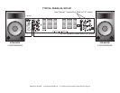
15. Mode Switch - This switch controls the amplier’s operating mode. The
amplier can operate in three dierent modes; Mono Bridge, Stereo, or Parallel
Mono. The amplier is shipped in stereo mode.
16. Air Vents - These vents allow hot air to exit the amp. Do not place any-
thing in front or obstruct these vents.
17. AC Cord - Plug this cable into a standard wall outlet. Check that the voltage
in your area matches the ampliers required voltage.
Fuse Holder - This housing stores a 12 amp protective fuse. Never defeat the
fuse, the fuse is designed to protect the electronics in the event of severe power
uctuations. Always be sure to replace the fuse with an exact match as the one
being replaced, unless otherwise told to do so by an authorized American Au-
dio® service technician.
16