


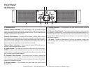
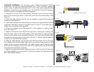
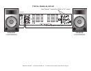
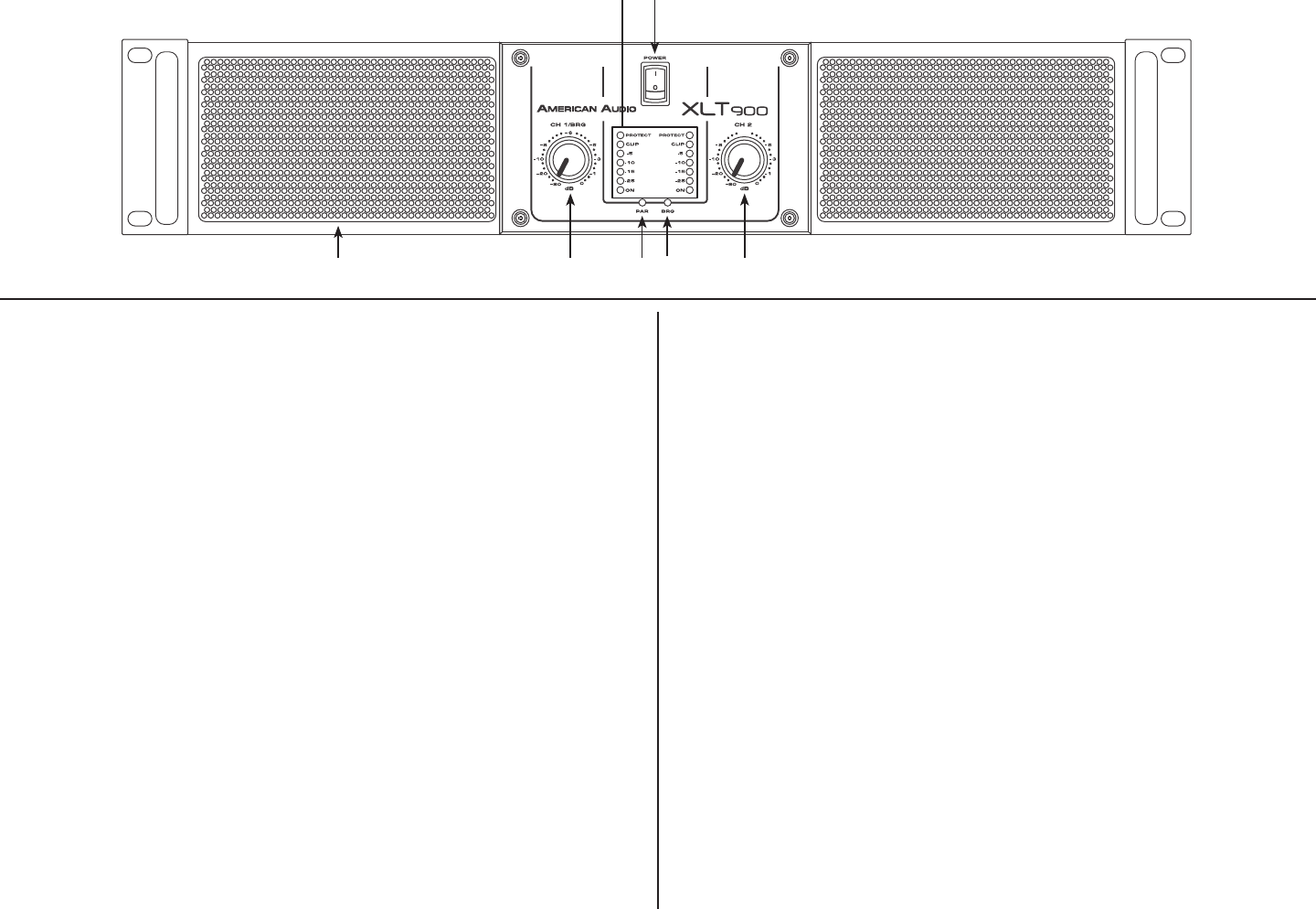
1. Indicator LEDs -
Channel Protect Indicator - The red Protect LED will begin to glow
when the channel goes into protect mode. When the channel goes into
protect mode all output for that channel will turn o. This is to protect any
speakers connected to the channel.
Channel Clip Indicator - This red LED will begin to ash when channel
one begins to overload (clip). At this point channel one will begin to dis-
tort. Under heavy clipping activity lower the channel one gain control to
reduce the risk of damage to your speakers and amplier. This LED may
glow when the unit has been turned o, this is normal.
Channel Signal Indicators - These yellow & green LED’s will glow ac-
cording to the average signal output.
2. Power Switch - This switch is used to control the units main power.
NOTE: The amp must always be turned on last in a audio set up, and
turned off rst in a audio set up. Before powering down the amp, turn the
gain controls to the lowest position.
3. Channel 2 Gain Control - This rotary knob is used to control the
output signal of channel two. Turning the knob in a clockwise direction
will increase signal output. Before powering down the amp, turn the gain
control to the lowest position.
4. Bridge Indicator - This indicator will glow when the amp is set to
Bridge Mode.
©American Audio® - www.americanaudio.us - XLT Series Power Amplifier User Manual Page 5
Front Panel
XLT Series
5. Parallel Indicator - This indicator will glow when the amp is set to
Parallel Mode.
6. Channel 1 Gain Control - This rotary knob is used to control the out-
put signal of channel one. Turning the knob in a clockwise direction will
increase signal output. This gain control is also used when the amp is in
Bridge Mode. Before powering down the amp, turn the gain control to
the lowest position.
7. Air Inlet - These air inlets draw in air from the outside to help cool
down the amp as it is running. Do not place anything in front or obstruct
these inlets.
Figure 1
1
5 4 3
2
6
7