


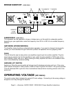

OPERATION
CONFIGURING THE AMPLIFIER
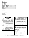
A 4-position dip switch on the rear panel allows you to configure certain amplifier characteristics.
A diagram on the rear panel shows the individual switch functions and settings..
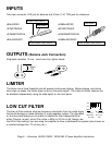
LOW-CUT FILTER: Setting position 1 to “ON” enables the low-cut
filter on channel 1 and “OFF” disables it. Position 4 does the same
for channel 2.
LOW-CUT FILTER FREQUENCY SELECTOR: When
setting position 1 or 4 to “ON” then position 2 or 3 up to cut-off of 30 Hz and down is for 50 Hz.
BUILT IN PROTECTION
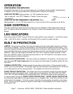
LIMITER: During signal overload, the limiter will reduce the input audio signal enough to minimize
the amount of clipping. During normal operation, the limiter does not affect the audio signal. It will
allow brief clipping of peaks and will only activate when continuous, hard clipping occurs. When the
signal amplitude decreases enough that clipping ends, the limiter will deactivate and cease its gain
reduction. When the input signal overloads, the “CLIP LED’s” indicate a signal overload. At this
time, the “LIMITER” switch on the front panel should be in the “ON” position or the master volume
should be lowered to reduce distortion.
INPUT/OUTPUT PROTECTION: The input circuits are isolated by 10k resistors. An ultrasonic net-
work decouples RF (radio frequency) from the output and helps keep the amplifier stable with reac-
tive loads.
THERMAL PROTECTION: Variable-speed fans provides cooling airflow. During low level output
the fan runs at normal speeds. During high output and as heat raises, (exceeding 90°C), the fan will
run at high speed to aid the cooling process. The amplifier will mute until it cools down.
SHORT CIRCUIT PROTECTION: The Output Short Circuit Protection protects the output devices
from short circuits and stressful loads. During short circuit protection, the “CLIP LED” and “PRO-
TECT LED” will light simultaneously indicating amp fault. All channel output will be interrupted (i.e.
no sound output), during the
“
SHORT CIRCUIT PROTECTION.” SHORT CIRCUIT PROTECTION
can usually be traced back to the signal output line (i.e. Speaker Line). Check the line from the out-
put terminal to the speaker. If this line is good, check the internal speaker connections and compo-
nents. A short circuit will usually be traced to a bad cable or a bad speaker and is rarely traced to
the amplifier itself.
30 50
LOW CUT FREQUENCY
GAIN CONTROLS
The gain controls are located on the front panel and are calibrated in DB of attenuation from full
gain. It is best to adjust the amplifier so no “hissing” is heard from speakers with no music being
played.
LED INDICATORS
Each channel has 6 LEDS. 2 green LED and 2 yellow LED for level indication, 1 red LED for power
clips, 1 red LED for short / overload, and the green LED at center for power indicator.
Page 7 • American AUDIO V3000 / V2000 MK II Power Amplifier Instructions