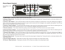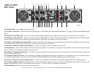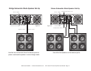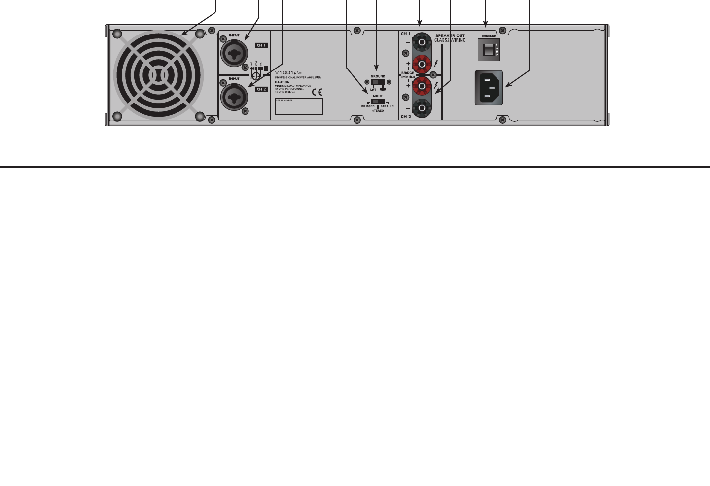
Figure 4
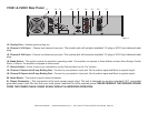
V1001 & V2001 Rear Panel
13 14 15 16 17 18 19 20 21
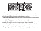
13. Cooling Fans - Variable speed cooling fan.
14. Channel 1 XLR Input - Channel one balanced input jack. This combo jack will accept a standard 1/4 plug or XLR 3-pin balanced male
plug.
15. Channel 2 XLR Input - Channel two balanced input jack. This combo jack will accept a standard 1/4 plug or XLR 3-pin balanced male
plug.
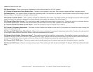
16. Mode Switch - This switch controls the amplifier’s operating mode. The amplifier can operate in three different modes; Mono Bridge, Parallel
Mono, or Stereo. The amplifier is shipped in stereo mode.
17. Ground Switch - If hear a hum or any interference, put the Ground switch in the “On” postion .
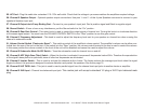
18. Channel 1 Output Jack/5 way Binding Post - Connect to your speaker’s input jack. Red is positive signal and Black is negative signal.
19. Channel 2 Output Jack/5 way Binding Post - Connect to your speaker’s input jack. Red is positive signal and Black is negative signal.
20. Reset Button - This button is used to reset the breaker.
21. Power Connector - This connection is the main power supply input. The unit is designed to accept a standard I.E.C. removable
grounded power cord. Be sure that your local power matches the unit’s required power. NEVER REMOVE THE GROUND PRONG
FROM THE POWER CABLE, DOING SO MAY RESULT IN IMPROPER OPERATION
©American Audio® - www.americanaudio.com - V-01 Series™ Power Amplifier User Manual Page 10


