


©American Audio® - www.americanaudio.com - VLP 2500 Power Amplifier User Manual Page 6
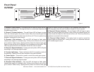
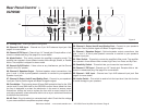
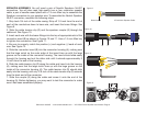
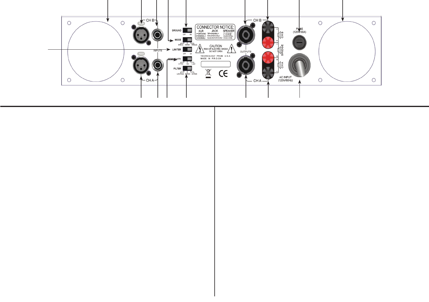
Rear Panel Control
VLP2500
21. Cooling Fans - Dual high speed cooling fans
22. Channel 2 XLR Input - Channel two 3-pin XLR balanced input jack. See
page 9 for more details.
23. Channel 2 TRS Input - Channel two 1/4” female jack. Excepts either a bal-
anced or unbalanced plug. See page 9 for more details.
24. Mode Switch - This switch controls the amplier’s operating mode. The
amplier can operate in three different modes; Mono Bridge, Stereo, or Parallel
Mono. The amplier is shipped in stereo mode.
25. Ground On/Off Switch - If hear a hum or any interference, put the Ground
switch in the “On” postion .
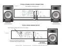
26. Channel 2 Speakon Output - Optional speaker output connections. Use
pins 1+ and 1- of this 4-pole Speakon connector to connect to your speaker’s
Speakon input jack.
27. Channel 2 Output Jack/5 way Binding Post - Connect to your speaker’s
input jack. Red is positive signal and Black is negative signal.
28. Fuse Holder - This housing stores 30 amp GMA protective fuse for the 120V
version and 15 amp GMA fuse for the 230/245V version. Never defeat the fuse,
the fuse is designed to protect the electronics in the event of severe power
uctuations. Always be sure to replace the fuse with an exact match as the
one being replaced, unless otherwise told to do so by an authorized American
Audio® service technician.
29. AC Cord - Plug this cable into a standard wall outlet. Check that the voltage
in your area matches the ampliers required voltage.
30. Channel 1 Output Jack/5 way Binding Post - Connect to your speaker’s
input jack. Red is positive signal and Black is negative signal.
31. Channel 1 Speakon Output - Optional speaker output connections. Use
pins 1+ and 1- of this 4-pole Speakon connector to connect to your speaker’s
Speakon input jack.
32. Filter Switch - This switch controls the amplier’s lter mode. The amplier
can operate in three different lter modes; High Pass, Low Pass, and By-Pass.
33. Sensitivity Switch - This switch lets you choose the input sensitivity.
34. Channel 1 TRS Input - Channel one 1/4” female jack. Excepts either a bal-
anced or unbalanced plug. See page 9 for more details.
35. Channel 1 XLR input - Channel one 3-pin XLR balanced input jack. See
page 9 for more details.
36. Limiter Switch - This switch is used to limit the input level. Use this function
to avoid damage to your speakers.
Figure 2
21 2128272625242322
30 2934 33 32 3135
36