


V1000
plus
V1000plus V1000
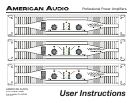
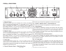
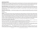
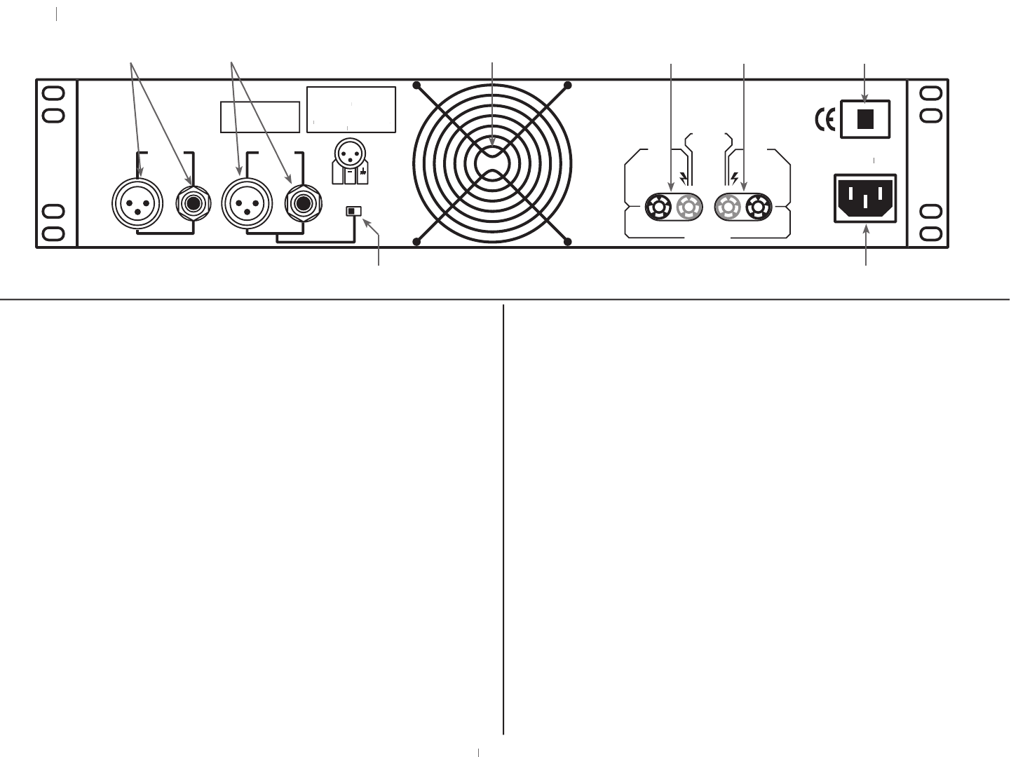
REAR PANEL
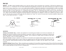
1. Channel 2 Input -
Connect the input source for channel two to either the balance
XLR or the balanced/unbalanced 1/4” input jacks. The 1/4” TRS
plug is configured as follows; Tip is positive, Ring is negative
and Sleeve is ground. The XLR jack is configured as follows; Pin
three positive, pin two negative, pin one ground. See page 9 for
more details on input configuration.
2. Channel 1 Input -
Connect the input source for channel one to either the balance
XLR or the balanced/unbalanced 1/4” input jacks. The 1/4” TRS
plug is configured as follows; Tip is positive, Ring is negative
and Sleeve is ground. The XLR jack is configured as follows; Pin
three positive, pin two negative, pin one ground. See page 9 for
more details on input configuration.
3. Cooling Fan -
This is a dual speed cooling fan. This fan is used to cool the
internal parts of the amplifier when in use. Never block the fan
in any way or mount in an enclose rack, doing so may cause the
amplifier to overheat and fail.
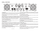
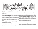
4. Channel 2 Speaker Output - 5 Way Binding Post -
Connect your channel two speakers to channel two output.
5. Channel 1 Speaker Output - 5 Way Binding Post -
Connect your channel one speakers to channel one output.
6. Circuit Breaker -
This breaker is designed to protect the amplifier and your speak-
ers in the event of an AC overload. In the event of an electrical
overload the breaker will pop-out. To reset the breaker, push it in.
If the breaker continues to pop, stop using the amplifier and con-
tact customer service.
7. Mono-Bridge/Stereo Selectable Switch -
This switch changes the amplifier operating mode from either
stereo or mono bridge. Amplifiers arrive to you preset in the ste-
reo operation mode.
8. A/C Power Input -
Plug this cable in to a standard 110~120v wall outlet. Be sure
that supplied voltage matches that of the required voltage of you
amplifier. Never plug your amplifier in to a wall outlet that does
not match the required voltage of your amplifier, serious damage
may occur to your unit.
Diagram 2
1000 W
A
1000 WA1000 W
TTS
ATTSA
BRIDGE
MONO
120V~60Hz
6
A
M
P
CAUTION
4 OHMS MINIMUM IMPEDANCE PRE CHANNEL
4 OHMS MINIMUM IMPEDANCE IN MONO BRIDGE MODE
OUTPUT
INPUT
CH
1
W
ARNING:
WARNING:W
T
O REDUCE
THE
RISK OF FIRE OR ELECTRICAL
SHOCK DO NOT
EXPOSE
SHOCK DO NOT EXPOSE SHOCK DO NOT
THIS
EQUIPMEN
T T
O RAIN OF MOIS-
TURE
A
VIS: RISQUE DE CHOC ELECT
AVIS: RISQUE DE CHOC ELECTA
-
VIS: RISQUE DE CHOC ELECT-VIS: RISQUE DE CHOC ELECT
TRIQUE - NE P
AS OUVRIR.
TRIQUE - NE PAS OUVRIR.TRIQUE - NE P
P2
P3
P1
+
- +
-
+
-
+
+
CH 1
CH 2
PROFESSIONAL POWER AMPLIFIER
STEREO BRIDGE
STEREO BRIDGE
STEREO BRIDGE
INPUT
CH
2
6
5
4
3
2
1
7
8
American Audio
®
- www.americandj.com - V
plus
- www.americandj.com - Vplus - www.americandj.com - V
Series Amplifiers Power Amplifier User Manual Page 6