


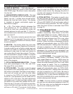
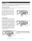

12. SEARCH BUTTONS -
This search button allows you to quickly
scan backwards through a track.
This search button allows you to quickly
scan forwards through a track.
13. TRACK BUTTONS -
This button is used to select a track.
Tapping this button will back-skip to the previous
track, holding down this button will rapidly back-
skip through the tracks on a CD.
This button is used to select your
desired track. Tapping this button will forward
skip to the next track, holding down this button
will rapidly forward skip through the tracks on
your CD.
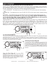
14. RELOOP BUTTON - If a LOOP has been
made (see setting a LOOP on page 17), but the
CD Player is not actively in LOOP mode (a loop is
not playing), pressing the RELOOP BUTTON
will
instantly reactivate the LOOP. To exit loop, press
the OUT BUTTON (15). LOOP and RELOOP
will appear in the LCD DISPLAY (4) when the
RELOOP function is available.
15. LOOP OUT BUTTON - This button is used to
set the ending point of a loop. A loop is started
by pressing the IN BUTTON (3),
pressing the OUT
BUTTON set the loop ending point. The loop
will continue to play until the OUT BUTTON
is
pressed once again.
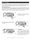
16. PLAY/PAUSE BUTTON - Each press of the
PLAY/PAUSE Button causes the operation to
change from play to pause or from pause to play.
While in play mode the green play LED will glow,
and while in pause mode the green play LED will
flash.
17. CUE - Pressing the CUE button during play-
back immediately pauses playback and returns
the track to the last set cue point (see setting a
CUE POINT, page 18).
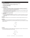
18. OPEN/CLOSE (TRANSPORT TRAY OPEN/
CLOSE) - This button is used to open and close
the transport tray. NOTE: The TRANSPORT TRAY
(1) will not open when a CD is already inserted,
unless the drive mechanism is in “Pause” or
“Cue” mode to prevent accidentally stopping the
music during playback.
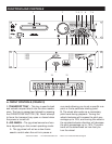
19. POWER SWITCH - This switch is used to
control the unit's main power.
20. AUDIO OUT R & L - These jacks are used
to send a left and right output signal. Use these
jacks to send an audio signal to a mixer or
receiver. The red colored jack represents the right
channel output and white jack represents the
left channels output. Used together these signal
reproduce a stereo signal.
21. DIGITAL OUT - This jack sends a digital
stereo out signal. Use this connection to create
near perfect copies of your disc to a Mini disc,
CD-R, or any other recording device with a digital
input.
22. VOLTAGE SELECTOR - Because power
supplies vary from location to location a voltage
selector switch has been incorporated in the unit's
design. This switch can select a voltage input of
115v or 230v to accommodate the two major
power source. Always be sure to disconnect the
power plug before changing the voltage.
*Only dual voltage units have this switch.
23. POWER CONNECTION - This is the main
power connection. Only use the supplied polar
-
ized power cord. Use of any power cord may
result in sever damage to the unit. Be sure the
local power source matches the units’ required
power.
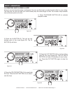
24. TIME BAR INDICATOR - This bar visually
details the time defined in the TIME METER
(29,
30, & 31). As with the TIME METER (29, 30, & 31
),
this bar is also dependent on the selected time
function REMAIN OR TOTAL. This bar will begin
to flash when 15 seconds of a track remain and
will begin to rapidly flash when three seconds of
a track remain. The flashing bar is a great visual
reminder a track is about to end. The flashing bar
will function regardless of which time mode the
unit is in.
25. SINGLE INDICATOR - This indicates the unit
is in single play mode, the unit will play a single
track and return to CUE mode. If the
SINGLE
FUNCTIONS AND CONTROLS
©American Audio® - www.americanaudio.com - MCD-110™ Instruction Manual Page 10