


PROFESSIONAL POWER AMPLIFIER
VLP2500
FHE 9B?F FEM;H
'& '+
9>7
&Z8
'&
,
)
'
.&
)&
'+
FHE9B?FFEM;H
'&'+
9>8
&Z8
'&
,
)
'
.&
)&
'+
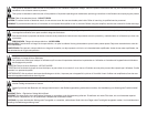
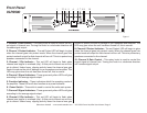
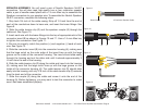
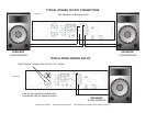
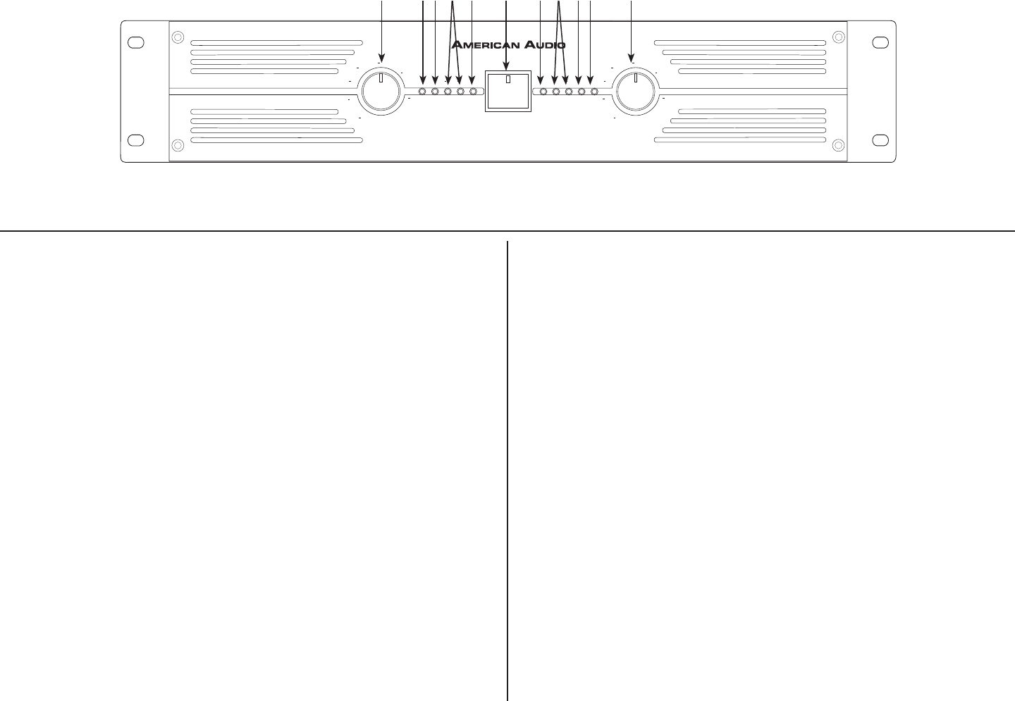
1. Channel 1 Gain Control - This rotary knob is used to control the out-
put signal of channel one. Turning the knob in a clockwise direction will
increase signal output.
2. Channel 1 Protect Indicator - The red Protect LED will begin to glow
when the channel goes into protect mode. When the channel goes into
protect mode all output for that channel will turn off. This is to protect any
speakers connected to the channel.
3. Channel 1 Clip Indicator - This red LED will begin to ash when
channel one begins to overload (clip). At this point channel one will be-
gin to distort. Under heavy clipping activity lower the channel one gain
control to reduce the risk of damage to your speakers and amplier. This
LED may glow when the unit has been turned off, this is normal.
4. Channel 1 Signal Indicators - These green and yellow LED’s will glow
according to the average signal output.
5. Function Indicators - These indicators detail the operating mode of
the amplier. These LEDs will also function as a power indicator.
6. Power Switch - This switch is used to control the units main power.
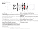
7. Channel 2 Signal Indicators - These green and yellow LED’s will glow
according to the average signal output.
8. Channel 2 Clip Indicator - This red LED will begin to ash when
channel one begins to overload (clip). At this point channel one will be-
gin to distort. Under heavy clipping activity lower the channel one gain
©American Audio® - www.americanaudio.com - VLP 2500 Power Amplifier User Manual Page 5
Front Panel
VLP2500
control to reduce the risk of damage to your speakers and amplier. This
LED may glow when the unit has been turned off, this is normal.
9. Channel 2 Protect Indicator - The red Protect LED will begin to glow
when the channel goes into protect mode. When the channel goes into
protect mode all output for that channel will turn off. This is to protect any
speakers connected to the channel.
10. Channel 2 Gain Control - This rotary knob is used to control the
output signal of channel two. Turning the knob in a clockwise direction
will increase signal output.
Figure 1
1 109875432 6 5