5
3.2 The Rear Panel
10. Fuse Holder /Voltage Selector
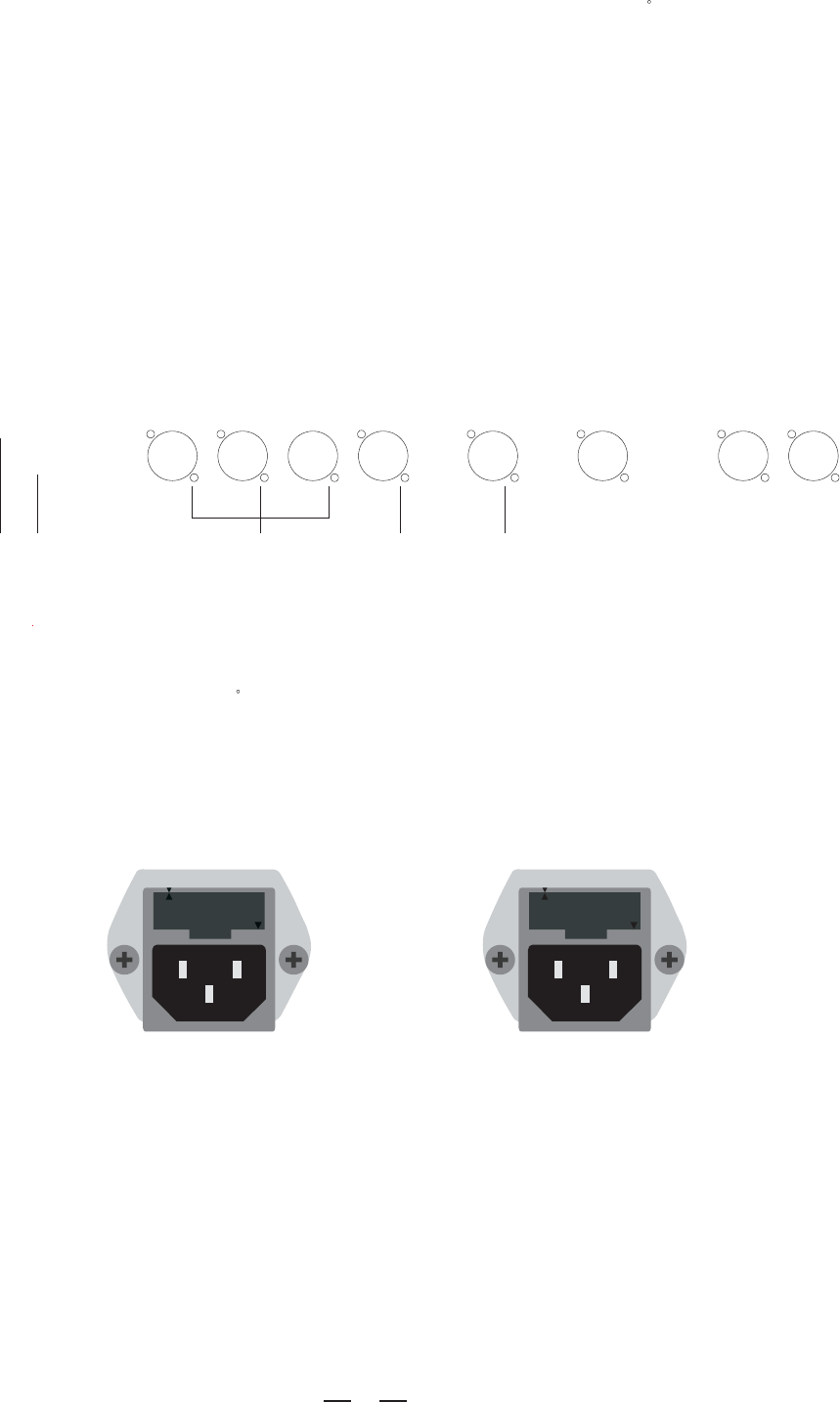
The fuse-holder above the AC connector on the rear of the chassis has 3 triangular markers(please refer to
the
above pictures), with two of these triangles opposing each other, your unit is set to the operating voltage
printed
next to these markers.
110-120V
220-240V
THIS IS SET FOR
110V AC TO 120V
AC OPERATION
THIS IS SET FOR
220V AC TO 240V
AC OPERATION
220-240V
110-120V
10 11 12 13 14
5. L/M CROSSOVER FREQ. Control
6. Phase Inversion for Mid-High Output
These buttons will reverse the phase of the Mid and High frequencies output by 180 , so that, the middle and high
frequencies cancellation in some fields can be compensated for.
7. Sub CROSSOVER FREQ. Control
This knob adjusts the crossover frequencies of the Subwoofer way from 50Hz to 250Hz.
8. Subwoofer Output Gain Control
This knob is used to attenuate or boost the subwoofer output gain.
9. Subwoofer Low Cut Switch
Engage this button to add a 30Hz Low Cut filter in the Subwoofer way.
Your unit may have the AC voltage selector (~115V/60Hz or ~230V/50Hz) built into the Fuse Holder. To change,
pull fuse-holder out and rotate 180 , then push in again.
technician, in the event of a fault or changing the supply voltage. If the fuse continues to blow after replacing, disc-
ontinue use of this unit before repaired.
This knob adjusts the Low/Mid crossover frequencies from 70Hz to 1kHz, based on which, the Low/Mid frequ-
encies can be output separately.
Caution: The fuse protecting the AC supplies circuits of this unit. The fuse can only be changed by a qualified
INPUT 2
WOOFER HIGHOUT 1 MID OUT 1
INPUT 1
LOW OUT 1HIGH OUT 2 MID OUT 2 LOW OUT 2


