


4
1. INTRODUCTION
With -Q you have acquired an indispensable toll to add clarity and flexibility to your music. The -Q 5 bandsLTO LTO
parametric equaliser will provide precise audio signal control to fixed sound installation, live performance and studio
applications. Thanks to the use of selected and expensive components the performances of -Q are worth muchLTO
more than its price: Variable Q controls allow you to notch out unwanted frequencies while sweepable frequency control
add maximum flexibility to your mix.
2.FEATURES
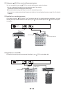
Mountable in one standard rack unit 19"
1/4" TRS type jack and balanced XLR connectors available
Led Meter (12 LED) to read input and output
Low cut and high cut filters available to cancel unwanted frequencies
Bypass function to connect automatically input and output
Optimum transparency of the audio signal and minimum phase shift insured by the parallel architecture of the filters
Switch-on button on every single band
Constant Q principle combination
5 bands of equalisation fully parametric (gain, frequency, Q) for studio and live applications
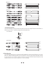
The frequency range of the single 5 bands is overlapping. This will allow extreme boost or attenuation
3.ELEMENT CONTROLS
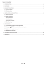
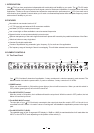
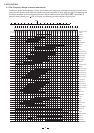
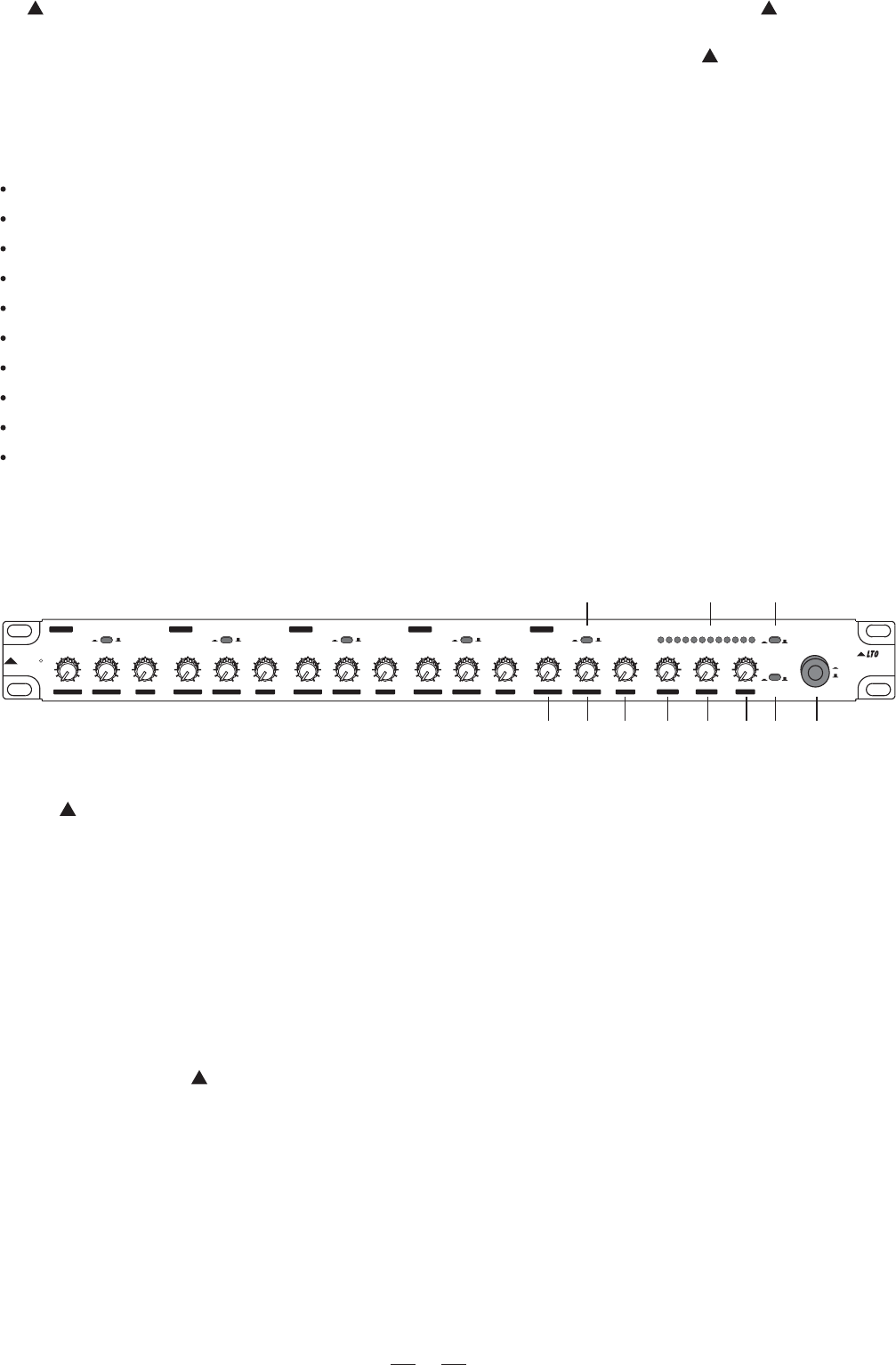
3.1 The Front Panel
Your -Q includes 5 channels of equalisation. 3 rotary controls and 1 switch are present in each channel. TheLTO
Master Section includes the power switch, 2 push-on switches, 3 rotary controls and 12 LED's.
When you set this switch in ON position (green light on) the unit will be turned on. When you set this switch in
OFF position (green light off) the unit will be turned off.
With this control in ON position, the Led Meter will read the output level. With this control in OFF position, the Led
Meter will read the input level.
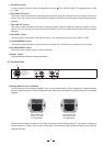
The input jack of your -Q is directly connected to the output jack when this control is OFF or if the unit is notLTO
connected to the AC socket. It is used to cause a "hard-bypass" and disable the equalisation process in the signal
path.
1.POWER switch
2.The INPUT/OUTPUT control
3.The AUDIO IN/OUT control
11 4 2
1
3
56
7
8910
The readable range of this 12 segments LED display is -30dB to +18dB. As mentioned before it will read either the
INPUT or the OUTPUT level depending on the position of the switch (2).
4.The INPUT/OUTPUT LEVEL
R
LTO
AUDIO
I / O METER
INPUT / OUTPUT LEVEL (dB)
-30 -24 -18 -12 -6 -3 0 +3 +6 +9 +12+18
INOUT/ INOUT/ INOUT/ INOUT/ INOUT/
Hz
OCTAVE OCTAVE OCTAVE OCTAVE OCTAVE
dB dB dB dB dB
110
45
150
25030
20 400
1.2 1.2 1.2 1.2 1.2
00000
0.03 0.03 0.03 0.03 0.03
1.6 1.6 1.6 1.6 1.6
-15 -15 -15 -15 -15+15 +15 +15 +15 +15
-5 -5 -5 -5 -5
-10
-10 -10 -10 -10
+5 +5 +5 +5 +5
Hz Hz
260
120 360
600
70
60
1K
720
350
1K
1.6K
200
150 2.5K
KHz
2.3
1.0
3.1
4.80.6
0.5 8.0
KHz
5.1
2.2
7.0
121.3
1.0
20
POWER
ON
OFF
20Hz - 400Hz
BAND1 BAND2
BAND3
BAND4
BAND5
60Hz - 1KHz
150Hz - 2.5KHz
500Hz - 8KHz
1KHz - 20KHz
FREQUENCY FREQUENCY FREQUENCY FREQUENCY FREQUENCY
BANDWIDTH BANDWIDTH BANDWIDTH BANDWIDTH BANDWIDTH
5-BAND PARAMETRIC
EQUALIZER
Q
IN
OUT
IN
OUT
IN
OUT
IN
OUT
IN
OUT
LEVELLEVEL LEVEL LEVEL LEVEL
0
-10
-15 +15
+10
+5
dB
INPUT
-5
+10
+10 +10 +10
75
Hz
50 110
25 200
40010
LOW CUT
10
7
15
22
3.5
2.5 30
KHz
HIGH CUT
+10
INPUT
OUTPUT
IN
OUT