


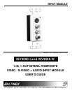

INPUT MODULE
400-0113-003
7
INSTALLING YOUR ISV3000 6
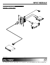
The ISV3000s will operate successfully as long as
all cables are attached properly and other technical
specifications are maintained. The ISV3000s use
terminal block connectors on the back which allow
an easy connection to different types of projectors
or monitors using ALTINEX cables.
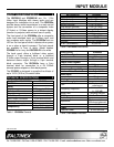
4.1 COMPOSITE (C-VIDEO) INPUT & OUTPUT
The ISV3000 accepts a C-Video, loop-insulated
input through a yellow RCA female connector and
offers a buffered C-Video output through a 2-pin
terminal block on the back of the ISV3000.
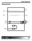
2-PIN TERMINAL BLOCK CONNECTIONS
PIN OUTPUT SIGNAL
1
C-Video
2
Shield/Return
4.2 S-VIDEO INPUT & OUTPUT
The ISV3000 accepts an S-Video input through a
4-pin Mini DIN connector and offers a buffered
S-Video output through a 3-pin terminal block on
the back of the ISV3000.
3-PIN TERMINAL BLOCK CONNECTIONS
PIN OUTPUT SIGNAL
1
Luma
2
Shield/Return
3
Chroma
4.3 AUDIO INPUT & OUTPUT
The ISV3000 accepts audio input and offers
balanced stereo output through a terminal block
connector on the back panel. There are two RCA
female connectors (red and white) for audio input,
which may be returned to an amplifier. A 5-pin
terminal block is available for stereo audio
transmission to the main sound system.
5-PIN TERMINAL BLOCK CONNECTIONS
PIN OUTPUT SIGNAL
1
+L (Left Channel)
2
-L (Left Channel)
3
SIGNAL RETURN
4
+R (RIGHT Channel)
5
-R (RIGHT Channel)
4.3 POWER INPUT CONNECTOR
The ISV3000 Input Module has a 2-pin terminal
block for connection to a 9 V 500 mA external
power adapter. A selection of several power
adapters is available for different countries from
110 VAC to 240 VAC.
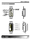
4.4 POWER/SIGNAL PRESENT LED
The ISV3000 Input Module has an LED on the front
panel which provides feedback to the user. When
power is connected to the ISV3000, the LED will
turn red. When a video source is connected to the
ISV3000, the LED will turn green, indicating that
the unit is receiving a signal.