


SPECIAL APPLICATION
400-0442-006
8
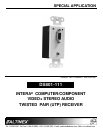
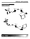
INSTALLING YOUR DS801-111 6
Step 1. Determine the best location for the
DS801-111. Where possible, locate the
TP Transmitter as close to the video
source as possible and the DS801-111 as
close to the receiving component as
feasible.
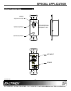
Step 2. Apply power to the 2-pin terminal block on
the rear of the DS801-111. The
Power/Signal Present LED should be on
and red.
Step 3. Connect the receiving display to the
output of the DS801-111 using a
high-quality video cable.
Step 4. Connect the audio amplifier or speakers
to the audio jack on the DS801-111.
Step 5. Run a UTP-type (CAT-5/CAT-5e) cable
from the 4TP INPUT on the DS801-111
Receiver to the 4TP OUTPUT on the TP
Transmitter.
NOTE: Ensure good signal transmission
by routing the cable to avoid any
sharp angles, creases, or bends.
Step 6. Connect the TP Transmitter per its
installation instructions. In the case of the
DS801-111, when the TP signal from the
DS801-110 is applied, the Power/Signal
Present LED will turn from red to green
indicating a signal is present.
Step 7. The units are now operational.
OPERATION 7
The DS801-111 requires only one adjustment to be
made for optimal performance. The adjustment is
video equalization for long cable lengths.
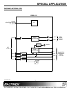
7.1 VIDEO EQUALIZATION
Video equalization is provided to fine-tune the
displayed image on the remote display.
Typically, for short cable runs the equalization
will be set to near minimum.
Start by setting the equalization to minimum on
both units. Adjust the equalization on the
receiver first. This adjustment should at least
allow the receiving display to receive an image.
Then use the equalization on both units to
fine-tune the image for optimal quality.
TROUBLESHOOTING GUIDE 8
We have carefully tested and have found no
problems in the supplied DS801-111. However, we
would like to offer suggestions for the following:
8.1 NO DISPLAY
Cause 1: The source has a problem.
Solution: Check the source and make sure
there is a signal present and all
source connections are correct. If
the source is working and there is
still no display, see Cause 2.
Cause 2: The path has a problem.
Solution: Connect the transmitter directly to
the receiver using a short UTP
patch cable. If the image is good,
there is a problem with the cable.
Otherwise, see Cause 3.
Cause 3: Cable connections are incorrect.
Solution: Make sure that cables are properly
connected. Also, make sure that the
continuity and wiring are good. If
there is still no display present, see
Cause 4.