


DISTRBUTION AMPLIFIERS
5
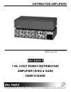
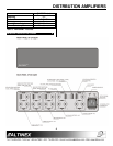
4.1 INPUT/OUTPUTS
The outputs of the DA1322AT allow signals to be
driven through 100 feet or more of cable
depending on cable quality and the source signal
resolution. The DA1322AT uses 5-BNC
connectors for each input and output representing
red, green, blue, and separate horizontal and
vertical sync. When passing an RGBS format
signal, simply use the horizontal channel to pass
composite sync.
4.2 CHANNEL DIP SWICTHES
Each channel (RED, GREEN, and BLUE) of the
DA1322AT has four dip switches: AC/DC, TERM,
GAIN, and EQLZ.
The AC/DC switch is used to select AC or DC
coupling of video signal through a distribution
amplifier.
The TERM switch is used to terminate or
unterminate RED, GREEN, & BLUE inputs with 75
Ohms.
The GAIN switch is used to set gain to 1 or 1.3.
The EQLZ switch is used to compensate for
longer cable runs.
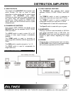
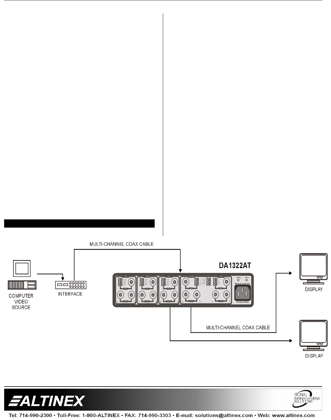
APPLICATION DIAGRAM 5
4.3 SYNC CONTROL SWITCHES
The DA1322AT has separate Sync control
switches: TERM H, C SYNC, TERM V, and SYNC
G.
The TERM H switch is used to terminate or
unterminate horizontal sync input with 75 Ohms.
The TERM V switch is used to terminate or
unterminate vertical sync input with 75 Ohms.
The C Sync switch is used with composite sync.
The Sync G switch is used with sync on green.
4.4 BANDWIDTH
Offering a minimum video bandwidth of 350 MHz
and typical bandwidth close of 500 MHz, the
DA1322AT allows even very high resolution video
signals to pass without degrading the image
quality.
4.5 POWER
Designed with a universal power input connector,
the DA1322AT offers a built-in linear power supply
with continuous operation at 95V to 240V.