


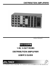

DISTRIBUTION AMPLIFIERS
5
4.1 SYNC POLARITY SWITCH
The SYNC POLARITY switch is located on the
back panel of the DA1203RM. It has two
switching positions — one designated (+) and
the other (-). By setting the sync polarity switch
to (+), the signal is processed unchanged and
the sync polarity of the output signal matched
the sync polarity of the unit. By setting sync
polarity to (-) the sync polarity of the output is
changed to the opposite of the input.
4.2 SYNC LEVEL SWITCH
The SYNC LEVEL switch is also located on the
back panel of the DA1203RM and has two
positions for switching — sync level of 2V and
sync level of 4V. Most often a 4V sync level is
used. This should be considered as default
setting. The 2V setting allows compatibility with
some older equipment that would be overdriven
if a stronger signal were used.
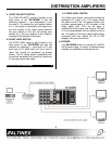
APPLICATION DIAGRAM 5
4.3 VIDEO LEVEL SWITCH
The Video Level Switch can be set to either the
standard 0.7V output or to 1.0V output. When
the switch is set in the 1.0V output position, this
provides approximately a 35% increase in the
video signal level. This can be used in
installations where cable runs exceed 150 feet.
It is not recommended that this switch be set in
the 1.0V position for shorter cable lengths as the
increased level may reduce the life of CRT
displays if they are over-driven.
4.4 POWER
The DA1203RM offers an internal 90-140/200-
240V power supply. A variety of different power
supplies are available for international use.