


SPECIAL APPLICATION
400-0522-002
8
INSTALLING YOUR DA103-217 6
Step 1. Determine if the computer needs to
receive available video resolutions from
the display device or from the internal
memory of the DA103-217. Set the EDID
switch to INT for using the DA103-217
internal memory or EXT to use the display
resolutions.
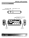
The switch is located on the side of the
unit and is accessible through a
rectangular opening.
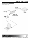
Step 2. Using the video cable provided, connect
one end to the display and the other end
to the output of the DA103-217.
Step 3. Connect the long cable from the source to
the DA103-217 video input.
Step 4. Apply power to the DA103-217 using the
power adapter provided. The
Power/Signal Present LED will be RED if
there is power and no signal and GREEN
if a signal is present.
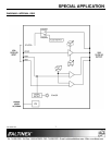
Step 5. Set the adjustment potentiometers as
follows:
EQ................. Minimum (full CCW)
GAIN ............. Minimum (full CCW)
SYNC ADJ .... Midway (50%)
Step 6. If the image is visible, start by adjusting
the EQ until the image is clear. A 250 ft
(76 m) cable will require near maximum
equalization.
If there is no image, start by slowly
increasing the SYNC ADJ. Stop adjusting
when the image is visible.
Step 7. While viewing the image on the display,
fine-tune the image using the EQ and
GAIN adjustments for the best image.
Step 7. Next, fine-tune the SYNC ADJ for the best
image/screen position.
Step 8. The DA103-217 is now operational.
OPERATION 7
The DA103-217 will operate successfully as long
as cables are attached properly and other technical
specifications are followed.
The adjustments on the DA103-217 Line Receiver
are available to fine-tune the output image and to
compensate for errors induced by cable quality,
cable length, and variations in equipment.
7.1 ADJUSTMENTS
7.1.1 EQ
Video equalization is provided to fine-tune the
displayed image on the remote display.
Typically, for short cable runs the equalization
will be set to near minimum. Cable lengths up to
250 ft (76 m) will require near maximum
equalization.
7.1.2 GAIN
Video gain is provided to restore signal level and
brightness to the remote display. Typically, this
adjustment is made after the equalization has
been set.
7.1.3 SYNC ADJ
The sync threshold adjustment allows changes
to be made in the sync processing circuitry and
to help recover and compensate for degraded
signals. Always start this adjustment with the
potentiometer set to the 50% position and make
adjustment in small increments.