


6
Operating Manual 6125A and 4200A Multi-Channel Power Amplifier
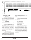
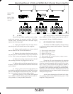
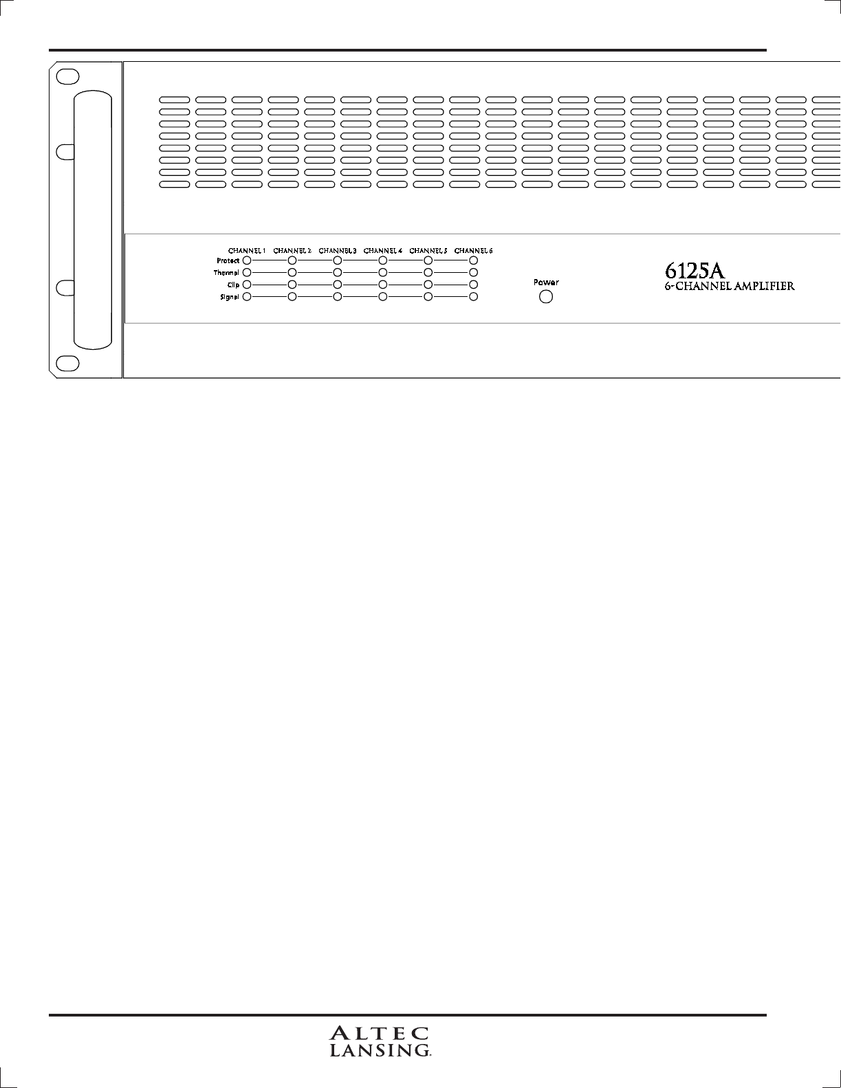
6. FRONT PANEL FEATURES
6.1 Power Switch
When the unit is switched on there is a five sec-
ond delay, during which time the PROTECT circuit will
activate, disconnecting the speakers from the amplifier
output. When turning off the amplifier, the load is removed
instantly, and the protect LED will briefly turn on as the
power supply discharges.
6.2 Signal Indicator
The signal present LEDs illuminate at an input
level of about 13mVrms (-35.5dBu).
6.3 Clip Indicator
The clipping LEDs illuminate at an input level of
about 870mVrms (+1.0dBu), with all channels driven by
1KHz into 8Ω. This indicates that the signal processing
circuitry has determined output levels to be approaching
the available power supply rails and has begun to “soften”
signal peaks. Actual onset of “hard” clipping depends on
audio program and total load impedance and does not oc-
cur until the signal processing circuitry can no longer com-
pensate, which means that signal integrity can be
maintained even if the clipping indicators illuminate for
short periods of time.
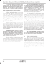
6.4 Thermal Status Indicator
The thermal LEDs illuminate when the tempera-
ture of any one of the heat sink extrusions reaches 85 to
90°C. Both channels of the affected amplifier module will
shut off until the measured temperature drops below about
70°C. The amplifier should be able to maintain proper
operation at an ambient room temperature of 50°C (122°F)
or less with typical audio program and all channels driven
into 4Ω.
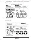
6.5 Protect Indicator
The protect LEDs illuminate when the fault moni-
toring microprocessor has determined that one of the fol-
lowing conditions exists:
- Power supply undervoltage
- Power supply overvoltage
- Output overcurrent
- Heat sink overtemperature
- Unacceptable DC output content
- Unacceptable high frequency output content
- AC power interruption
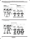
Because the signal processing module used in the
6125A and 4200A amplifiers processes two channels si-
multaneously, a fault in one channel will result in a pro-
tect condition for both channels processed by the same
module, ex. channels 1-2, 3-4, and 5-6 (6125A only). Thus
there will never be a case where only one of the amplifier
channels is shown in protect mode. When a pair of protect
LED's are illuminated, internal relays have removed the
channel pair's speaker loads from the amplifier output and
connected the speakers to ground. If the fault is isolated
to one module (channel pair), the other channels will re-
main unaffected.