


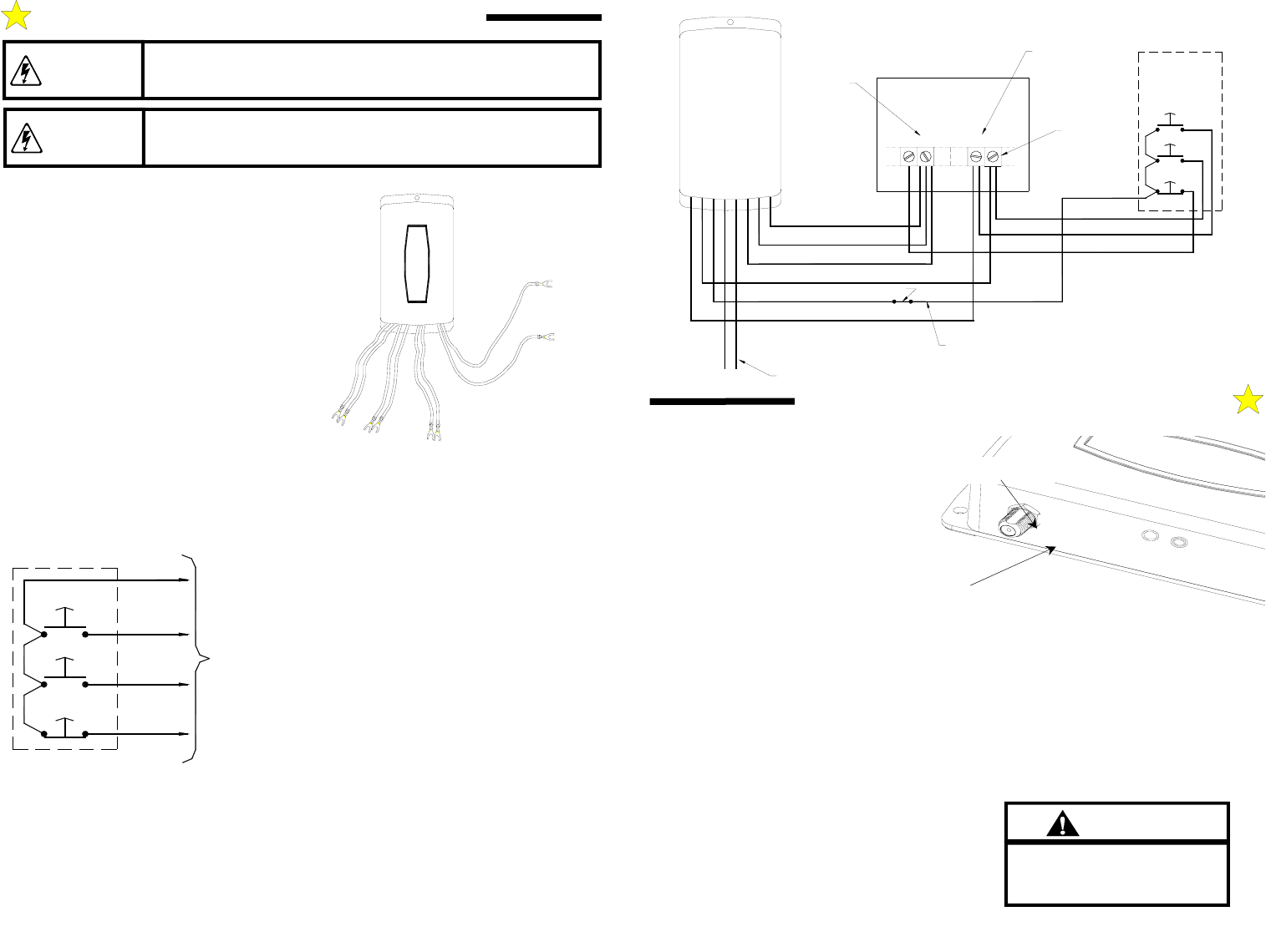
The MVP-831E receiver functions as a 3-button
station. Three sets of isolated contacts are provided;
normally open contacts for the OPEN
PUSHBUTTON (orange wires); normally open
contacts for the CLOSE PUSHBUTTON (black
wires); normally closed contacts for the STOP
PUSHBUTTON (gray wires). Refer to Figure 1.
For special STOP circuit applications, normally
open contacts are available from the factory.
Typical 4-wire 3-button stations are wired as shown
in Figure 2. Number 18 gauge wire or heavier must
be used for wiring the control stations and the MVP-
831E receiver to the door operator. Smaller gauge
wire may cause operational problems, especially
when multiple 3-button stations are used. For
typical installations the MVP-831E receiver is
mounted near the door operator, away from any high
voltage conduits or steel support beams. For
wiring, follow the steps below and refer to Figure 3.
1. In the door operator control panel, locate the wire
connecting the door operator to the 3-button station
COMMON. Note its location and remove.
2. Connect one of the gray wires from the MVP-831E to the
wire just removed from the pushbutton COMMON.
3. Connect the following wires from the MVP-831E to the
operator 3-button COMMON (as shown in Figure 3):
ONE ORANGE (OPEN)
ONE BLACK (CLOSE)
ONE GRAY (STOP)
4. Connect the remaining MVP-831E black wire to the
CLOSE pushbutton terminal in the door operator control
panel.
5. Connect the remaining MVP-831E orange wire to the OPEN pushbutton terminal in the door operator
control panel.
6. Finish the wiring by connecting 24 VAC to the red and white wires of the MVP-831E receiver.
BEFORE APPLYING POWER, CHECK ALL CONNECTIONS AND INSTALL THE
ANTENNA.
IMPROPER WIRING COULD CAUSE ELECTROCUTION OR
DAMAGE TO CIRCUITRY. FOLLOW LOCAL BUILDING AND
ELECTRICAL CODES.
WARNING
Figure 1
106548
R
E
D
W
H
I
T
E
G
R
A
Y
B
L
A
C
K
O
R
A
N
G
E
24 VAC
STOP
CLOSE
OPEN
STOP
CLOSE
OPEN
TERMINAL STRIP
TO OPERATOR
WALL PUSHBUTTON STATION
Figure 2
105113
MVP-831E RECEIVER WIRING INSTRUCTIONS
TO PREVENT ELECTROCUTION DISCONNECT POWER AT
FUSE BOX AND DOOR OPENER BEFORE WIRING
PERMANENTLY.
WARNING
DOC. 112049 REV A
Page 2 of 4
Refer to individual manuals for
transmitter installation, coding and
user instructions.
Important
Learning Transmitter Codes
The MVP-831E receiver is capable of
learning the codes from up to 8 different
Allstar Open/Close/Stop transmitters. The
transmitters may be any combination of
Allstar’s MVP, Classic or original dip-
switch type Open/Close/Stop transmitters
(Models 8833-O/C/S, 8833C-O/C/S, 831,
733, 639, and/or 53S).
Match the receiver operating frequency
with the transmitter operating frequency.
Pre-program the transmitter (or set the DIP
switches) according to the instructions that
accompanied the transmitter.
For transmitters that can operate multiple doors
(Models 8833C-O/C/S, 733 639, and 53S), make sure
the selector switch(es) is (are) positioned for the
desired door you want to operate before starting the
receiver programming steps below.
Learn/Erase Button
Indicator LED
Programming The Receiver
Step 1: Momentarily press and release the Learn
button. The LED will turn on.
Step 2: Using a programmed transmitter, press any
one of the transmitter buttons (OPEN, CLOSE, or
STOP). When the receiver learns the transmitter code,
the LED will turn off. The receiver has automatically
learned the two remaining buttons.
Step 3: Repeat to add additional transmitters with
different codes if desired.
Erasing the Receiver’s Memory
Step 1: Press and HOLD the Learn button. The
indicator LED will turn on.
Step 2: When the LED turns off (after approximately 5
seconds), release the Learn button.
RECEIVER PROGRAMMING INSTRUCTIONS
DOC. 112049 REV A
Page 3 of 4
COMMERCIAL
STOP COM CLOSE
OPEN
OPERATOR
RECEIVER
MVP-831E
OPEN
STOP
CLOSE
WALL PUSH
BUTTON
ORANGE
BLACK
GRAY
BLACK
GRAY
ORANGE
WHITE
RED
COMMON
24 VAC
Removed Wire
(See Step 1)
Step 2
Step 3
Step 4
Step 5
Step 6
STATION
Figure 3
106549